Astable oscillator using transistor, capacitor and resistor and change duty cycle automatically

Thread Starter

hhsting

Joined Apr 25, 2024
395
Why 5.7v if the load requires 4.7 volts?
If you go back I have 2 power supply. This battery is one of the two. The battery is backup. To do this
I have a diode at vout so 4.7+.7 =5.4 therefore 5.4V at the vout. If I have vout then on cathode side of the diode i have 4.7V. Diode cathode is where the load. The diode is at vout. Can we go back to how you got value of R1,R3, R4?
 

sghioto

Joined Dec 31, 2017
8,737
If you go back I have 2 power supply. This battery is one of the two. The battery is backup. To do this
I have a diode at vout so 4.7+.7 =5.4 therefore 5.4V at the vout. If I have vout then on cathode side of the diode i have 4.7V. Diode cathode is where the load. The diode is at vout. Can we go back to how you got value of R1,R3, R4?
I will shortly but first you need to show me this power supply schematic how the battery and primary supply are configured.
 

sghioto

Joined Dec 31, 2017
8,737
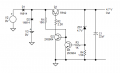
This is my suggestion using diode isolation.
This works as long as V2 is slightly higher in voltage than V3.
There is a loss of appx .7 volts from the battery supply when V2 is OFF.
A better way is to use a mosfet to isolate the battery supply or use a schottky diode like a 1N5817 for D2
It shows a loss of appx 0.3 volts at 200ma.
1755611663247.png
EDIT: Added comment about using a 1N5817 for D2.
 
Last edited:

Ian0

Joined Aug 7, 2020
13,227
This is my suggestion using diode isolation.
This works as long as V2 is slightly higher in voltage than V3.
There is a loss of appx .7 volts from the battery supply when V2 is OFF.
A better way is to use a mosfet to isolate the battery supply.
View attachment 354457
If you only need 4.7V output, then 0.7V loss on the diode is of no consequence.
 

sghioto

Joined Dec 31, 2017
8,737
But you still answer my question how was values of R1, R3, and R4 selected
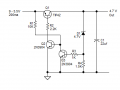
R4 was adjusted at 1.5K to get the output at 4.7 volts. Depends on the zener diode used and actually worked out to 4.75v on the breadboard.
R1 seemed about right based on R2.
R3 is a current limit for the base of Q3.
 

BobTPH

Joined Jun 5, 2013
11,609
If you really want a discrete component buck converter, the way to do it is implement a comparator, which is about the same complexity as your multivibrator, then make a hysteric (bang bang) buck converter. These are quite simple and can have a variable reference voltage with no extra complexity.
 

Thread Starter

hhsting

Joined Apr 25, 2024
395
R4 was adjusted at 1.5K to get the output at 4.7 volts. Depends on the zener diode used and actually worked out to 4.75v on the breadboard.
R1 seemed about right based on R2.
R3 is a current limit for the base of Q3.
Their is one flow to this circuit. Battery still have juice below 5.5V and the circuit stops and does not utilize full potential of the battery as opposed to to the earlier circuit with buck and boost converter it will utilize until battery voltage is 0.7v
 

sghioto

Joined Dec 31, 2017
8,737
Their is one flow to this circuit. Battery still have juice below 5.5V and the circuit stops and does not utilize full potential of the battery as opposed to to the earlier circuit with buck and boost converter it will utilize until battery voltage is 0.7v
I seriously doubt that below 5.5 volts. Will that battery deliver 200ma when at 5.5 volts or lower?
Have you actually tested that?
 

sghioto

Joined Dec 31, 2017
8,737
Thats what buck boost converter does it steps up voltage. I have NOT tested the actual original circuit since i had question on it
At .7 volt a lithium ion battery is dead and probably ruined.
Most likely that 9 volt battery you refer to is appx 8.4 volts when fully charged and would need to be recharged at appx 6.4 volts to be maintained properly.
 

Thread Starter

hhsting

Joined Apr 25, 2024
395
At .7 volt a lithium ion battery is dead and probably ruined.
Most likely that 9 volt battery you refer to is appx 8.4 volts when fully charged and would need to be recharged at appx 6.4 volts to be maintained properly.
But buck boost converter should step up voltage below 5.5v and original circuit still power load as oppose to your circuit it wont. As to how much below is something needs to be tested. Could be 1 v or could be 2V who knows
 

sghioto

Joined Dec 31, 2017
8,737
But buck boost converter should step up voltage below 5.5v and original circuit still power load as oppose to your circuit it wont. As to how much below is something needs to be tested. Could be 1 v or could be 2V who knows
Well OK, good luck with that.
 

BobTPH

Joined Jun 5, 2013
11,609
Thats what buck boost converter does it steps up voltage. I have NOT tested the actual original circuit since i had question on it
To deliver 5.5V at 200mA from 0.7V, the battery would have to put out over 1.6A. More likely 3A at the efficiency you are likely to get. Can your dead battery do that? You are dreaming if you think you can extract that kind of power from a 9V battery that has run down below about 7V.
 
Top