Facebook
 Google
 GitHub
 Linkedin
Hey guys,
My electrical theory has failed me and I have been left scratching my head looking at the following astable multivibrator circuit. Just to summarize its current state:
- C1 is charging
- C2 is dis-charging
- Q1 is off
- Q2 is on
Whats got me confused (and I'm sure it's a simple explanation) is the voltages..
Is the base of Q1 drawing voltage or is it giving up voltage? See figure 1 below:

Then we have the voltage across the 1K resistor (3rd leg from the left) sitting at 6.59V. How can that be if the source voltage is only +5V? See figure 2:

And finally we have the voltage across the capacitor:

I guess to summarize my question; why do we have -1.59V on the base of Q1 and 6.59V across the 1K resistor and then 1.6V across the cap. Obviously its to do with KVL, although its been quite a few years since I have analysed a circuit. Any clarification will be greatly appreciated!
Thank you in advance")
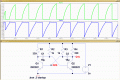
My electrical theory has failed me and I have been left scratching my head looking at the following astable multivibrator circuit. Just to summarize its current state:
- C1 is charging
- C2 is dis-charging
- Q1 is off
- Q2 is on
Whats got me confused (and I'm sure it's a simple explanation) is the voltages..
Is the base of Q1 drawing voltage or is it giving up voltage? See figure 1 below:
Then we have the voltage across the 1K resistor (3rd leg from the left) sitting at 6.59V. How can that be if the source voltage is only +5V? See figure 2:
And finally we have the voltage across the capacitor:
I guess to summarize my question; why do we have -1.59V on the base of Q1 and 6.59V across the 1K resistor and then 1.6V across the cap. Obviously its to do with KVL, although its been quite a few years since I have analysed a circuit. Any clarification will be greatly appreciated!
Thank you in advance