Assessing an unknown transformer

Thread Starter

someonesdad

Joined Jul 7, 2009
1,583
I occasionally need a transformer and have a few in the junk box to select from. I do the following things to "get to know" a particular transformer:

  1. Measure the resistance between all the terminals.
  2. Use a function generator to apply a 60 Hz sine wave (usually 1 to 5 Vrms) to the (assumed) primary and measure the voltages on the secondaries. This gives me the ratios.
The two things I want to know before using a transformer are:

A. Is it safe to use with the voltage I plan to apply?

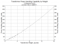
B. How much power can I apply to it safely?

I can measure the following characteristics of the transformer:

1. Mass
2. Physical dimensions
3. Diameter of the wire used to make the windings (sometimes)
4. Inductance of the windings

Can you experienced folks suggest any rules of thumb to use with these data to make an engineering judgment to provide approximate answers the two questions A and B? Are there some other measurements a hobbyist could make that would give more insight?
 

Bychon

Joined Mar 12, 2010
469
I have asked the same question, and the answers I get are weak. The best I have so far is 20 watts per pound and stop using more current when the output voltage is 10% lower than it was with no load.

I know this is weak. Sorry. It's the best I can do.
 

retched

Joined Dec 5, 2009
5,207
There is an art to this, and Im no artist.

I have heard the 20 watts per pound before, I have also heard of taking the area measurement and the wire gauge on the secondary to determine max current.

I would love to see some real number on this.
 

t_n_k

Joined Mar 6, 2009
5,455
With respect to the primary voltage you can safely apply - that is a tough one unless the windings are clearly marked.

One approach might be - If you have a Variac then you can slowly increase the primary voltage whilst observing the magnetising losses [you'd need a power meter or equivalent measurement setup]. You would look at incremental changes as the magnetising flux density increases - M27 non-oriented transformer steel has a typical loss of about 0.6-1.0 Watt per pound at 60Hz and 10,000 Gauss [1 Tesla] - depending on the lamination gauge from Ga 29 to 24. If you observe losses significantly higher than these you might have reached a voltage limit. Not much to go on though.

Plus you'd have to work out the relative steel to copper mass in the total unit mass. I guess you can make a reasonable guess at that ...
 
Last edited:

Thread Starter

someonesdad

Joined Jul 7, 2009
1,583
I'd like to turn it into an engineering project -- I'll do the work if you guys critique my ideas, approach, and data. If others want to volunteer to help, that's fine too.

Problem statement: provide engineering guidelines, rules of thumb, and heuristics to help a hobbyist make a reasonable estimate of the ratings and type of an unmarked transformer. The goal is to help the hobbyist use the transformer in a safe manner in a project.

The emphasis is on the hobbyist, as a professional will probably have access to tools and knowledge the hobbyist won't. This implies that methods of how to do things "on the cheap" are probably preferred over fancy tools and techniques. The scope of the study can probably be limited to single-phase transformers that operate on the order of a kilowatt or less.

The output can be some or all of the following:

  • Tutorial document with real data on how to make your own assessments. The tutorial can also include a practical introduction to the different types of transformers, how to identify them, and how they're used (or, just refer to the AAC tutorial stuff if the consensus is that it's adequate).
  • Instructions on building your own equipment to aid in these assessments.
  • How to interpret any markings that are found on a transformer -- or where to find information on a particular manufacturer's product line if the part number of the transformer is given.
  • Practical information on the construction of typical transformers. Some of this might come from dissection of working transformers with known characteristics, some might come from design manuals.
  • Summary document of what was learned, what was overlooked, and the various sources of information used, such as web sites, textbooks, forum posts, and other literature.
Some things to look at or think about:

  • Measure the (incremental?) power loss in the winding(s) by increasing the applied AC voltage; changes in slope may indicate where operating points are. (t_n_k's suggestion)
  • Look at the change in the shape of the magnetizing current waveform as it increases (this can reflect the BH curve of the core material). See http://www.allaboutcircuits.com/vol_2/chpt_9/1.html.
  • Inductance of windings -- what does this tell you about the construction/use? (I know that the voltage ratio of the windings is equal to the square root of their inductance ratio.) How about capacitance between windings? Again, what does this tell you about construction/use?
  • DC resistance and/or impedance of windings -- what can you deduce from measuring them? (See http://www.allaboutcircuits.com/vol_2/chpt_9/2.html)
  • Can calorimetric/power measurements be made that tell you anything useful? For example, run the transformer in still air at various power levels and measure the temperature rise of the steel laminations. Or submerge the thing in mineral oil and measure the temperature rise of the oil at given loads (right -- someone's going to go to this trouble and mess :)).
  • How about using a Variac and a resistive load? Measure the transformer's power efficiency as a function of applied voltage and load resistance. What does this tell you about where its operating point(s) might be?
  • When the transformer is run at various powers, what can you conclude (if anything) from the measurement with a scope of the current and voltage waveforms on the primary and secondaries?
  • If the winding is swept with a sweep function generator (and perhaps an audio amplifier), resonances may be found (and there should be one because of the inductance and stray capacitance). Does the location and sharpness of these resonances tell you anything useful about the transformer's construction and/or use?
  • Are the E-core shapes of transformers standardized in size? (I found a web link somewhere that leads me to believe there may be some standardization.) Then, given the thickness of the laminations, their size, and their number, what can we say about the transformer's performance (if anything). It would be impractical for the hobbyist to determine the steel grade though...
  • What are some of the practical design engineering texts for transformers? (At least those that would be within technical reach of the hobbyist with a general engineering/science background.)
  • If you can measure the wire diameter of the windings, are there current density considerations or dissipated power per unit volume that might give you an idea of upper operating points?
 

Bychon

Joined Mar 12, 2010
469
Trying to be helpful...

One of the first considerations of a transformer designer is about how much core material will be required to transfer the power with limited losses caused by core saturation. From this, you can assume something about the core being optimized in terms of $ by making it as small as possible for the power to be transferred.

There are definite, standard sizes of E-core.

There are standards of current density in the windings. I heard someone say, "1000 circular mils per amp" about 35 years ago. Of course, this can vary by manufacturer. One exception is the "breaking wire" rule. I asked my transformer winder, "What is the smallest size wire does not give you problems with breaking?" He answered, "30 gauge" and we used that to supply 10 milliamps.
 

Bychon

Joined Mar 12, 2010
469
continuing...

An exception to the "smallest core" rule happened when a toroid core did not have enough window to hold all the windings. A larger core was used.

E-cores have standard sizes, and standard proportionalities. If a center leg is this wide, the outside legs will be this other size, the backbone will be some other size, and these proportions are used for all sizes by that manufacturer of laminations.

Here is a recepie for a transformer: Goal is a linear power supply that produces 18 VDC @ 1 amp. core is size EI-112 That means a critical dimension is 1&1/8th inch.
The bobbin is called, "NY13" That determines the stack height of the laminations.
Primary winding is 547 turns of #23 wire.
Secondary winding is 220 turns of #21 wire (with a center tap).

I have 16 pages of these recepies if you want more.
 

studiot

Joined Nov 9, 2007
4,998
Couple of 'old hand' formulae.

\(A = \frac{{\sqrt W }}{{5.58}}\)

A is the core cross section in sq inches and W is the VoltAmp output.

\(E = \frac{{4.44FHNA}}{{100,000,000}}\)

E is the winding voltage
F is the mains frequency
H is the number of lines of magnetic flux per square inch of iron
N is the number of turns
A is the cross section area in sq inches of the core

If E is taken as 1 it gives the turns per volt for any winding on the core
 
Last edited:

Bychon

Joined Mar 12, 2010
469
If I remember correctly, the "area of the core" means the area of one leg, analogous to the circular mils in a wire. The area of the core is the cross-sectional area of a leg in the EI vocabulary.
 
If I remember correctly, the "area of the core" means the area of one leg, analogous to the circular mils in a wire. The area of the core is the cross-sectional area of a leg in the EI vocabulary.
EI laminations have 3 legs. The cross sectional area is the area of the center leg, the one that passes through the bobbin (if there is one). The two outer legs each have half the cross sectional area of the center leg.
 
The emphasis is on the hobbyist, as a professional will probably have access to tools and knowledge the hobbyist won't. This implies that methods of how to do things "on the cheap" are probably preferred over fancy tools and techniques. The scope of the study can probably be limited to single-phase transformers that operate on the order of a kilowatt or less.
What equipment would it be reasonable to expect a hobbyist to have to make transformer measurements like you propose?

Perhaps we could assume a lowest level hobbyist, who surely must be expected to have a volt-ammeter of some sort, and some resistors, capacitors, transistors, etc.

Then there would be the advanced hobbyist who has a scope and a variac, and what else?
 

retched

Joined Dec 5, 2009
5,207
A triple-beam or digital scale. and a micrometer to get wire gauges.

Thats about good for outputs.

There is a shareware program that I had years ago ,where you could input the width height and depth of the coil and wire gauge on primary and secondary coils, type of core, and it would spit out the estimated transformer power ratings.

Ive googled for a while, saw some things that looked close, but not the same program.
 

Thread Starter

someonesdad

Joined Jul 7, 2009
1,583
What equipment would it be reasonable to expect a hobbyist to have to make transformer measurements like you propose?
I made the following list up this afternoon:

The engineers/scientists can get all wrapped up in the technical design details of this stuff. However, we probably need to focus on the hobbyist's needs -- all he really wants is some guidelines on how to analyze and use a particular transformer.

Let's first look at what's available to the hobbyist.

Analog meters, resistors: can be used to make special test equipment.

DMM: general purpose measurement tool.

Impedance bridge: much less likely to have. Could build an inductance meter if they're really dedicated, as there are plans on the web.

Thermocouple/thermistor: use to measure temperatures.

Power supply: general purpose tool. Lots of suggestions on AAC and elsewhere on how to make one from e.g. a PC power supply.

Function generator: maybe. Can get used or build one. No doubt a 555-based square wave oscillator would be an excellent general-purpose tool.

Audio amplifier: stereo equipment.

Oscilloscope: only the intermediate/advanced folks will be likely to have this.

Variac: unlikely

Kill-a-Watt: useful for power & VA measurements

Selection of resistors and capacitors. Perhaps a handful of inductors.

Shunt: not too hard to make your own from Romex or stainless steel wire (Chromel is good too, as it's nearly the same as Nichrome).

1 A current source for measuring low resistances: build with voltage ref, op amp, power FET, and D cell for current.

Load resistors: few to none. But can get pretty cheap sand resistors at Radio Shack.

Measuring mass: it's not hard to build a balance, even sensitive ones (the hard part is getting a decent set of weights). Ohaus triple beam balances can be had for about $50 on ebay. Used postal scales can be found in second-hand stores.

Measuring dimensions: a 1 mm rule is excellent and, with e.g. a 4X loupe, can be read to 0.1 mm pretty well. A Dumaurier Micro-Mike is nearly ideal for wires, but they're pretty hard to find. If you know a little PostScript and have access to a laser or inkjet printer, you can make pretty accurate line widths on a piece of Mylar; with a loupe, this can be used to estimate wire sizes.
 
The power handling capability of a transformer is primarily determined by the area product of the core. This is the product of two areas: the cross sectional area of the core (center leg of EI laminations) and the area of the winding window. This product is referred to as the WaAc product. See page 4.3 of this document:

http://www.diegm.uniud.it/mattavelli/elettronica_industriale/Magnetica/CoreDesign.pdf

Typical commercial transformers of the sort a hobbyist might encounter will probably be wound on EI laminations. If the stack of laminations is the same height as the width of the center leg, the core is described as a "square stack". One will also find transformers with an "oversquare" stack.

See here for drawings of standard laminations:

http://www.tempel.com/products.asp?cat=11

The weight of a commercial transformer is related to the power handling capability, but the relationship is not linear. I extracted parameters for 43 small to moderate size transformers from the Stancor catalog and plotted power handling versus weight. I did a curve fit to the data points, and the plot is shown in the first and second attachments. The 20 pounds per watt rule of thumb works fairly well around the 3.5 pound region.

Note that this is the total transformer weight--iron plus copper, not just the iron.

I also did a curve fit to the same transformers with area product as the independent variable. The result is shown in the third attachment.

The ultimate determinant of power handling capability is the allowable hot spot temperature. With class A insulation, typical for the transformers the hobbyist is likely to encounter, the allowable hot spot temperature is 105° C.

What one could do is use the graph of power handling vs weight to get a good estimate. Then measure the DC resistance of a winding on the transformer at ambient (room temp), which will probably be around 20° C. Next apply the load determined from the graph for several hours. Quickly disconnect the power and load, and measure the DC resistance of the winding. The temperature of the winding can be determined with the formula:

\(Th = \frac{Rh}{Ra}(234.5+Ta)-234.5 +10\)

Where Rh is the hot resistance of the winding, Ra is the resistance at ambient temperature (the starting temperature; room temperature), Ta is the ambient temperature, and Th is the hot spot temperature of the winding.

Since when the winding is hot, not all parts of it will be at the same temperature, the measured hot resistance will be a kind of average of the temperature of all the parts of the winding. A compensation for this effect is made by adding 10° to the calculated temperature.

After doing this a couple of times, one can interpolate and find the power supplied by the transformer which will just raise the hot spot temperature to 105°; that will be the rated power of the transformer.

Or, you can just use the graph and allow a safety factor.
 

Attachments

Last edited:
With respect to the primary voltage you can safely apply - that is a tough one unless the windings are clearly marked.

One approach might be - If you have a Variac then you can slowly increase the primary voltage whilst observing the magnetising losses [you'd need a power meter or equivalent measurement setup]. You would look at incremental changes as the magnetising flux density increases - M27 non-oriented transformer steel has a typical loss of about 0.6-1.0 Watt per pound at 60Hz and 10,000 Gauss [1 Tesla] - depending on the lamination gauge from Ga 29 to 24. If you observe losses significantly higher than these you might have reached a voltage limit. Not much to go on though.

Plus you'd have to work out the relative steel to copper mass in the total unit mass. I guess you can make a reasonable guess at that ...
What I've always done is to monitor the current with a scope as the applied voltage from the variac increases. It's obvious when saturation is beginning, and knowing that commercial transformers are operated at that point when rated voltages are present on the windings, we have thus determined the rated voltages.

I would think that any hobbyist who has a variac probably also has a scope.

But, in the absence of a scope, this trick works well:

Safety warning: When doing tests with a variac, which is an autotransformer, whose output is not galvanically isolated from its input, don't connect a scope to any circuit powered by the variac without isolation unless you have a scope with isolated inputs, and know how to safely probe line connected circuitry.

A simple isolation transformer can be made with two typical step-down transformers. Say, for example, that you have a couple of 120:12 volt transformers. Connect the 12 volt winding of one of the transformers directly to the 12 volt winding of the other. Now you can connect the 120 volt winding of one of the transformers to the line, and the 120 volt winding of the other will put out 120 VAC, but it will be isolated, and you can connect the ground clip of a scope to one side or the other of that isolated 120 volt output winding.

You can still get shocked if you get across the 120 volt output winding, but you won't blow a fuse or get molten droplets of copper in your face when you connect the scope ground clip.

The power which you can get out of this arrangement is, of course, limited to the power handling rating of the individual transformers. For example, if the transformers are rated 2 amps@12 volts on the secondary, then you can only pass 24 watts through this "isolation" transformer. And if you draw the full rated load of the two transformers, the "120" volts you get out will be reduced by the impedance of the transformers. If you're going to be doing this kind of thing a lot, get a "real" isolation transformer with suitable rating.

If you don't use an isolation transformer, then don't connect a scope to the circuit. But, you can still connect a voltmeter across the transformer winding you're testing if it's a portable, battery operated meter. Just connect everything, including the voltmeter, before you plug the circuit into the wall socket, and don't touch anything while it's plugged in.

Connect a 40 to 60 watt incandescent light bulb in series with a winding (not the primary) of the transformer. Energize the series combination with a variac. Measure the AC voltage across the winding with a meter. This is a case where an average responding meter is definitely better; a cheapie DMM is just the thing, or an older analog AC voltmeter. As you turn up the variac, the voltage across the winding will increase more or less linearly with the applied voltage. But, at a certain point the voltage will reach a distinct plateau, and won't increase much more. That voltage is approximately the rated voltage of the winding. The precision of this measurement is not great, but you can easily distinguish between a 12 volt winding and a 24 volt winding.

If you don't have a variac, then you can apply line voltage to the "light bulb-transformer winding" combination. Even then the voltage across the winding will be somewhat close to the rated voltage of the winding.

What's happening is that when the applied voltage is less than the rated voltage of that winding, the core doesn't saturate, and its impedance is higher than the light bulb. But, when a voltage higher than the rated voltage of the winding is applied, the core saturates, and its impedance drops, which tends to keep the voltage across the winding from rising much more.

The core does saturate when a high voltage is applied to the series bulb-winding combination. This can be seen in the two attached images.

The first shows the voltage across the winding when a relatively small voltage is applied by the variac. The second shows the saturation that occurs with a higher applied voltage (the trace from the first image is shown in gray). The peaks become taller but narrower , and an average responding voltmeter doesn't overemphasize the narrow but tall peaks like an RMS responding meter would. The peaks occur when the core de-saturates; saturation is occurring when the orange trace is more nearly horizontal, near the X-axis. It's as though saturation is clamping the voltage.

When the actual primary is subjected to this test, there is no noticeable plateau in the voltage across the winding as the variac voltage is increased, assuming that the variac can't produce much more than 120% of line voltage.

And, because the primary inductance of a typical transformer is usually measured in henries, and because the unloaded magnetizing current is small, the light bulb doesn't light up even with full line voltage applied. This gives a quick and safe (no danger of burning up a winding) test to locate the primary. If a transformer winding in series with a light bulb prevents the bulb from lighting when full line voltage is applied, then there won't be very much current drawn when that winding (and the other windings are unloaded) is connected to the line; you've found the primary. (If you've got a transformer with high voltage windings, a transformer left over from the days of vacuum tubes, this test may confuse one of the high voltage windings with the true primary.)

Of course, if the primary is located with this test, then we can just apply line voltage to the primary and measure the secondaries, without using the technique in the first part of the post.
 

Attachments

Last edited:

Thread Starter

someonesdad

Joined Jul 7, 2009
1,583
Electrician, this is marvelous information you've posted! I thank you for the effort you've put into it so far; I've started a document that I'll incorporate the information in (with your permission, of course) -- hopefully, I'll get it in reasonable enough shape to post here for everyone to use. Yesterday, I had a little time and did some exploring on the net and found some useful information. Alas, the dark overlord is cracking her whip on my back and I've been exiled to the yard for trimming and garden work; this takes precious time away from doing something useful, like playing with transformers. :p

I'm going to try to organize the document around the types of equipment used, as this will likely determine which tests can be done by an individual. I'll probably use two categories:

User with few resources: DMM, analog meters, can build needed specialized circuits as long as in the relatively easy category.

User with more sophisticated resources: scope, function generator, Variac, isolation transformer, etc.
 

Thread Starter

someonesdad

Joined Jul 7, 2009
1,583
I extracted parameters for 43 small to moderate size transformers from the Stancor catalog and plotted power handling versus weight.
Would you mind posting the actual data (plain text or CSV or spreadsheet is fine) so we can see which transformers you used? I assume you used the data from the Stancor site, right?
 
Electrician, this is marvelous information you've posted! I thank you for the effort you've put into it so far; I've started a document that I'll incorporate the information in (with your permission, of course) -- hopefully, I'll get it in reasonable enough shape to post here for everyone to use.
You have my permission to use whatever you want. I think Bill Marsden is working on a document concerning power supplies, and transformer info would probably useful there, too. See:

http://forum.allaboutcircuits.com/showthread.php?t=34047

Here's the Stancor catalog:

http://www.stancor.com/jsp/products.jsp

I took the data from the single secondary pages:

http://www.stancor.com/wrdstc/pdfs/Catalog_2006/Pg_002_4.pdf

I'll add data points as I find them from other sources. I'm going to see if the Triad site has similar catalog info.

The good thing about using that data rather than theoretical calculations is that this is typically what one will actually be using.

I should mention that another way to determine an approximate value for the power handling capability of an unknown transformer is to refer to the catalog pages of a manufacturer, such as the Stancor pages linked above, and find a transformer with the same construction style and dimensions as your unknown. Then your transformer will presumably have essentially the same power rating as the matching exemplar in the catalog.

I should also be sure that it's understood that the particular winding voltages and currents of a transformer have almost nothing to do with its power rating. What matters is maximum allowed hot spot temperature. So if the transformers being compared are all class A rated, then two transformers with the same dimensions, but different winding voltages, will have the same power rating. It's just a matter of size, insulation thermal class and cooling method (free air, forced air, etc.). This assumes that the transformers being compared are constructed with the usual methods--put as much copper in the winding window as possible, apportion the losses equally to the primary and secondary, etc. A transformer deliberately underwound to achieve a particular purpose, such as with extra insulation between primary and secondary to get a higher voltage withstand rating, will have lower power rating because there is nomex in there taking up space that could be occupied with copper otherwise. Another construction method that can result in lower power rating is split bobbin construction, which also reduces the packing factor.
 
Last edited:

Thread Starter

someonesdad

Joined Jul 7, 2009
1,583
All good points. I want to mention that I'm designing the document for the hobbyist (me!) who has an unmarked transformer in the junk box and wants to make an estimate of the capabilities of the transformer. Thus, the transformer is mostly a black box and the topics will be to discover as much as possible about it with the tools at hand.

I've already learned a number of things from various web pages, such as the practical equivalent circuit for transformers, and the open circuit and short circuit tests. However, Electrician, your work and thoughts here are going to lead to valuable pragmatic heuristics that probably aren't in a textbook anywhere (other than the author waving his hand and forcing the reader to go do all the work).
 

retched

Joined Dec 5, 2009
5,207
Well, I already have a spot on my bench for your finished product.

What a great idea. Keep up the good work, both of you.
 
Top