 Facebook
 Google
 GitHub
 Linkedin
Hi everybody,
It's my first time posting here on AAC
I'm somewhat uncertain about my design for Exercise 1.24 from the Art of Electronics.
The exercise says the following:
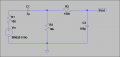
Design a two-stage "bandpass" RC filter, in which the first stage is highpass with a breakpoint of 100Hz, and the second stage is lowpass with a breakpoint of 10kHz. Assume the input signal source has an impedance of 100 ohms. What is the worst-case output impedance of your filter, and therefore what is the minimum recommended load impedance?
I've attached a picture of the current design I have at the moment. I just focused on just creating a bandpass filter with the breakpoint frequency specs such that the bandpass was slightly wider than specified to make up for uncertainty in component tolerances.
What does it mean when they say to assume the input signal source has an impedance of 100 ohms? Is it just like how my design has a 100 ohm resistor attached in front of the input voltage?
Does the current design suffice or am I missing the point somewhere?
Also, how do I figure out the answers to the questions?
It's my first time posting here on AAC
I'm somewhat uncertain about my design for Exercise 1.24 from the Art of Electronics.
The exercise says the following:
Design a two-stage "bandpass" RC filter, in which the first stage is highpass with a breakpoint of 100Hz, and the second stage is lowpass with a breakpoint of 10kHz. Assume the input signal source has an impedance of 100 ohms. What is the worst-case output impedance of your filter, and therefore what is the minimum recommended load impedance?
I've attached a picture of the current design I have at the moment. I just focused on just creating a bandpass filter with the breakpoint frequency specs such that the bandpass was slightly wider than specified to make up for uncertainty in component tolerances.
What does it mean when they say to assume the input signal source has an impedance of 100 ohms? Is it just like how my design has a 100 ohm resistor attached in front of the input voltage?
Does the current design suffice or am I missing the point somewhere?
Also, how do I figure out the answers to the questions?
Attachments
-
 11.2 KB Views: 52


