Thread Starter

Akshay447

Joined Feb 20, 2024
8
Welcome to AAC.

As you can see, many members are ready to help you but they can’t unless you provide enough information—and you haven’t.

We need:

  1. a BoM (Bill of Materials)—that is, a parts list of at least the major components with part numbers
  2. a schematic, or at least a clear wiring diagram
  3. the code, in [CODE] tags, which is best done using the Code option in the View attachment 315961menu, in the toolbar of the post editor.

It sounds like one of only a few things but guessing at which it could be is a waste of time. With sufficient information, guessing won’t be necessary.

Re-uploaded Receiver Sketch. Motors started moving again without recieving any signal from transmitter.
 

Attachments

Ya’akov

Joined Jan 27, 2019
10,262
Re-uploaded Receiver Sketch. Motors started moving again without recieving any signal from transmitter.
Please put the code in [CODE] tags as I described—forcing people to download files to help you isn’t a good thing and many if not most will give it a pass. You can edit your post to add that, and it is OK to leave the uploaded sketches in case someone wants to download them.
 

Thread Starter

Akshay447

Joined Feb 20, 2024
8
Please put the code in [CODE] tags as I described—forcing people to download files to help you isn’t a good thing and many if not most will give it a pass. You can edit your post to add that, and it is OK to leave the uploaded sketches in case someone wants to download them.
Code:
/*ARDUINO JOYSTICK CONTROLLED CAR (RECEIVER)
        
YOU HAVE TO INSTALL THE RF24 LIBRARY BEFORE UPLOADING THE CODE
   https://github.com/tmrh20/RF24/       
*/
#include <SPI.h>
#include <nRF24L01.h>
#include <RF24.h>
#define enA 2 
#define in1 3
#define in2 4
#define enB 7   
#define in3 5
#define in4 6
RF24 radio(8, 9); // CE, CSN
const byte address[6] = "00001";
char receivedData[32] = "";
int  xAxis, yAxis;
int motorSpeedA = 0;
int motorSpeedB = 0;
void setup() {
  pinMode(enA, OUTPUT);
  pinMode(enB, OUTPUT);
  pinMode(in1, OUTPUT);
  pinMode(in2, OUTPUT);
  pinMode(in3, OUTPUT);
  pinMode(in4, OUTPUT);
  Serial.begin(9600);
  radio.begin();
  radio.openReadingPipe(0, address);
  radio.setPALevel(RF24_PA_MIN);
  radio.startListening();
}
void loop() {
  if (radio.available()) {   // If the NRF240L01 module received data
    radio.read(&receivedData, sizeof(receivedData)); // Read the data and put it into character array
    xAxis = atoi(&receivedData[0]); // Convert the data from the character array (received X value) into integer
    delay(10);
    radio.read(&receivedData, sizeof(receivedData));
    yAxis = atoi(&receivedData[0]);
    delay(10);
  }
 
  // Y-axis used for forward and backward control
  if (yAxis < 470) {
    // Set Motor A backward
    digitalWrite(in1, HIGH);
    digitalWrite(in2, LOW);
    // Set Motor B backward
    digitalWrite(in3, HIGH);
    digitalWrite(in4, LOW);
    // Convert the declining Y-axis readings for going backward from 470 to 0 into 0 to 255 value for the PWM signal for increasing the motor speed
    motorSpeedA = map(yAxis, 470, 0, 0, 255);
    motorSpeedB = map(yAxis, 470, 0, 0, 255);
  }
  else if (yAxis > 550) {
    // Set Motor A forward
    digitalWrite(in1, LOW);
    digitalWrite(in2, HIGH);
    // Set Motor B forward
    digitalWrite(in3, LOW);
    digitalWrite(in4, HIGH);
    // Convert the increasing Y-axis readings for going forward from 550 to 1023 into 0 to 255 value for the PWM signal for increasing the motor speed
    motorSpeedA = map(yAxis, 550, 1023, 0, 255);
    motorSpeedB = map(yAxis, 550, 1023, 0, 255);
  }
  // If joystick stays in middle the motors are not moving
  else {
    motorSpeedA = 0;
    motorSpeedB = 0;
  }
  // X-axis used for left and right control
  if (xAxis < 470) {
    // Convert the declining X-axis readings from 470 to 0 into increasing 0 to 255 value
    int xMapped = map(xAxis, 470, 0, 0, 255);
    // Move to left - decrease left motor speed, increase right motor speed
    motorSpeedA = motorSpeedA + xMapped;
    motorSpeedB = motorSpeedB - xMapped;
    // Confine the range from 0 to 255
    if (motorSpeedA < 0) {
      motorSpeedA = 0;
    }
    if (motorSpeedB > 255) {
      motorSpeedB = 255;
    }
  }
  if (xAxis > 550) {
    // Convert the increasing X-axis readings from 550 to 1023 into 0 to 255 value
    int xMapped = map(xAxis, 550, 1023, 0, 255);
    // Move right - decrease right motor speed, increase left motor speed
    motorSpeedA = motorSpeedA - xMapped;
    motorSpeedB = motorSpeedB + xMapped;
    // Confine the range from 0 to 255
    if (motorSpeedA > 255) {
      motorSpeedA = 255;
    }
    if (motorSpeedB < 0) {
      motorSpeedB = 0;
    }
  }
  // Prevent buzzing at low speeds (Adjust according to your motors. My motors couldn't start moving if PWM value was below value of 70)
  if (motorSpeedA < 70) {
    motorSpeedA = 0;
  }
  if (motorSpeedB < 70) {
    motorSpeedB = 0;
  }
  analogWrite(enA, motorSpeedA); // Send PWM signal to motor A
  analogWrite(enB, motorSpeedB); // Send PWM signal to motor B
}
Code:
/*Arduino JOYSTICK CONTROLLED CAR (TRANSMITTER)
          
YOU HAVE TO INSTALL THE RF24 LIBRARY BEFORE UPLOADING THE CODE
   https://github.com/tmrh20/RF24/     
*/

#include <SPI.h>
#include <nRF24L01.h>
#include <RF24.h>
RF24 radio(8,9); // CE, CSN
const byte address[6] = "00001";
char xyData[32] = "";
String xAxis, yAxis;
void setup() {
  Serial.begin(9600);
  radio.begin();
  radio.openWritingPipe(address);
  radio.setPALevel(RF24_PA_MIN);
  radio.stopListening();
}
void loop() {
 
  xAxis = analogRead(A1); // Read Joysticks X-axis
  yAxis = analogRead(A0); // Read Joysticks Y-axis
  // X value
  xAxis.toCharArray(xyData, 5); // Put the String (X Value) into a character array
  radio.write(&xyData, sizeof(xyData)); // Send the array data (X value) to the other NRF24L01 modile
  // Y value
  yAxis.toCharArray(xyData, 5);
  radio.write(&xyData, sizeof(xyData));
  delay(20);
}
 

KeithWalker

Joined Jul 10, 2017
3,609
In the receiver program, the motor control inputs are not initialized to any value. They only receive a value after the signal has been received. Until then, the outputs are floating.
In the initialize section, after the inputs have been defined, write a digital low to in1, in2, in3 and in4. That will inhibit motor movement until a valid signal is received.
 

Ya’akov

Joined Jan 27, 2019
10,262
In the receiver program, the motor control inputs are not initialized to any value. They only receive a value after the signal has been received. Until then, the outputs are floating.
In the initialize section, after the inputs have been defined, write a digital low to in1, in2, in3 and in4. That will inhibit motor movement until a valid signal is received.
A quick look at the receiver code doesn’t reveal any way to know if there has been a change or not. So, it checks for data on the radio link, and if there isn’t any it jumps right to line 45 which would would be true and turn on a motor.

Did I miss something?
 

KeithWalker

Joined Jul 10, 2017
3,609
A quick look at the receiver code doesn’t reveal any way to know if there has been a change or not. So, it checks for data on the radio link, and if there isn’t any it jumps right to line 45 which would would be true and turn on a motor.

Did I miss something?
You are right. I guess I got lost in the spaghetti code. The program should loop until a valid signal is received, without changing any variables. It is still necessary to initialize the variables to avoid random motor movement.
 

Thread Starter

Akshay447

Joined Feb 20, 2024
8
In the receiver program, the motor control inputs are not initialized to any value. They only receive a value after the signal has been received. Until then, the outputs are floating.
In the initialize section, after the inputs have been defined, write a digital low to in1, in2, in3 and in4. That will inhibit motor movement until a valid signal is received.
Can you please do that for me. I am completely new
 

Ya’akov

Joined Jan 27, 2019
10,262
You are right. I guess I got lost in the spaghetti code. The program should loop until a valid signal is received, without changing any variables. It is still necessary to initialize the variables to avoid random motor movement.
It’s not the worst code I‘ve ever read but the loose style makes it pretty hard to read. That’s why I wasn’t certain I hadn’t missed something. It really should have been written with clear functions.
 

MisterBill2

Joined Jan 23, 2018
27,741
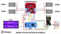
One immediate issue that I see looking at the system connection drawing is that the power to the arduino comes from the motor control board.
The problem with that is that it assures that the driver board is powered and able to drive the motors before the arduino is even able to initialize. That certainly is not how the system should be functioning.
So the apparent solution will be to alter the arrangement so that the motor driver module will not be powered until the arduino has had time to wake up and take control.
Making that happen will require a separate switch and power source for the arduino processor, and then a separate control device for the motor module power. This is an issue that we could not see until the connections were shown.
But it might be that the motor driver module has an "enable" , or "Enable outputs", control line that the arduino can control. That would be the simplest possible solution if it is available.

And note that this certainly looks like a hardware issue, based on the motor drive serving also as the power source for the arduino. Software is not likely to be the problem if it is not yet running.
 

geekoftheweek

Joined Oct 6, 2013
1,429
@MisterBill2 made a good point about the power. From the documentation I found the Nano should have it's own on board voltage regulator. Personally I would power the Nano directly from the batteries instead of through the regulator on the motor board..

Did you remove the jumpers from the enable pins on the board? The controllers come with jumpers installed that allow it to be used without a voltage on the enable pins. They will damage the Arduino output if they are not removed.

Once again I advocate the use of pull down resistors. The enable pins don't appear to have any internal that I can see in the datasheet or schematics of a generic L298N module. I'll admit I didn't read all the documentation I could find, but block diagrams don't show any (unless there is some other detail I missed that would make them redundant). That should prevent any issues at startup by itself not related to programming.

From what I can tell the Nano should default to all inputs at startup with no pull ups enabled according to the ATmega328 datasheet so there should be nothing from there to cause the motor to run without the program setting pins to output. The datasheet also specifies all outputs will default to 0 at startup also.
 

MisterBill2

Joined Jan 23, 2018
27,741
@MisterBill2 made a good point about the power. From the documentation I found the Nano should have it's own on board voltage regulator. Personally I would power the Nano directly from the batteries instead of through the regulator on the motor board..

Did you remove the jumpers from the enable pins on the board? The controllers come with jumpers installed that allow it to be used without a voltage on the enable pins. They will damage the Arduino output if they are not removed.

Once again I advocate the use of pull down resistors. The enable pins don't appear to have any internal that I can see in the datasheet or schematics of a generic L298N module. I'll admit I didn't read all the documentation I could find, but block diagrams don't show any (unless there is some other detail I missed that would make them redundant). That should prevent any issues at startup by itself not related to programming.

From what I can tell the Nano should default to all inputs at startup with no pull ups enabled according to the ATmega328 datasheet so there should be nothing from there to cause the motor to run without the program setting pins to output. The datasheet also specifies all outputs will default to 0 at startup also.
Certainly these are some important insights about dealing with the arrangement and interconnections.
 

KeithWalker

Joined Jul 10, 2017
3,609
The nano requires supply with a minimum of 7VDC. The L298N has a built-in LM7805 so it will also need a minimum supply of 7V. The voltage of two two 18650 Li-ion cells could drop as low as 6V which would cause all kinds of problems. This is not a very well designed project in hardware and software.
I recommend that the TS tries to learn about the components used in this project and the way it is programmed so that he can make it work correctly. He will learn nothing if we re-write the software for him.
The program should run in the loop(), searching for an input from the radio. If it receives data, it should call a function to activate the motors. If not, it should continue looping. If he decides not to do this, he must make sure the transmitter is activated before the receiver if he does not want to damage the motor controller.
 

Thread Starter

Akshay447

Joined Feb 20, 2024
8
The nano requires supply with a minimum of 7VDC. The L298N has a built-in LM7805 so it will also need a minimum supply of 7V. The voltage of two two 18650 Li-ion cells could drop as low as 6V which would cause all kinds of problems. This is not a very well designed project in hardware and software.
I recommend that the TS tries to learn about the components used in this project and the way it is programmed so that he can make it work correctly. He will learn nothing if we re-write the software for him.
The program should run in the loop(), searching for an input from the radio. If it receives data, it should call a function to activate the motors. If not, it should continue looping. If he decides not to do this, he must make sure the transmitter is activated before the receiver if he does not want to damage the motor controller.
Code:
/*ARDUINO JOYSTICK CONTROLLED CAR (RECEIVER)
        
YOU HAVE TO INSTALL THE RF24 LIBRARY BEFORE UPLOADING THE CODE
   https://github.com/tmrh20/RF24/       
*/
#include <SPI.h>
#include <nRF24L01.h>
#include <RF24.h>
#define enA 2 
#define in1 3
#define in2 4
#define enB 7   
#define in3 5
#define in4 6
RF24 radio(8, 9); // CE, CSN
const byte address[6] = "00001";
char receivedData[32] = "";
int  xAxis, yAxis;
int motorSpeedA = 0;
int motorSpeedB = 0;
void setup() {
  pinMode(enA, OUTPUT);
  pinMode(enB, OUTPUT);
  pinMode(in1, OUTPUT);
  pinMode(in2, OUTPUT);
  pinMode(in3, OUTPUT);
  pinMode(in4, OUTPUT);
    
// Initialize motor control inputs to a known state (LOW)
    
  digitalWrite(in1, LOW);
  digitalWrite(in2, LOW);
  digitalWrite(in3, LOW);
  digitalWrite(in4, LOW);
    
  Serial.begin(9600);
  radio.begin();
  radio.openReadingPipe(0, address);
  radio.setPALevel(RF24_PA_MIN);
  radio.startListening();
}
void loop() {
  if (radio.available()) {   // If the NRF240L01 module received data
    radio.read(&receivedData, sizeof(receivedData)); // Read the data and put it into character array
    xAxis = atoi(&receivedData[0]); // Convert the data from the character array (received X value) into integer
    delay(10);
    radio.read(&receivedData, sizeof(receivedData));
    yAxis = atoi(&receivedData[0]);
    delay(10);
  }
 
  // Y-axis used for forward and backward control
  if (yAxis < 470) {
    // Set Motor A backward
    digitalWrite(in1, HIGH);
    digitalWrite(in2, LOW);
    // Set Motor B backward
    digitalWrite(in3, HIGH);
    digitalWrite(in4, LOW);
    // Convert the declining Y-axis readings for going backward from 470 to 0 into 0 to 255 value for the PWM signal for increasing the motor speed
    motorSpeedA = map(yAxis, 470, 0, 0, 255);
    motorSpeedB = map(yAxis, 470, 0, 0, 255);
  }
  else if (yAxis > 550) {
    // Set Motor A forward
    digitalWrite(in1, LOW);
    digitalWrite(in2, HIGH);
    // Set Motor B forward
    digitalWrite(in3, LOW);
    digitalWrite(in4, HIGH);
    // Convert the increasing Y-axis readings for going forward from 550 to 1023 into 0 to 255 value for the PWM signal for increasing the motor speed
    motorSpeedA = map(yAxis, 550, 1023, 0, 255);
    motorSpeedB = map(yAxis, 550, 1023, 0, 255);
  }
  // If joystick stays in middle the motors are not moving
  else {
    motorSpeedA = 0;
    motorSpeedB = 0;
  }
  // X-axis used for left and right control
  if (xAxis < 470) {
    // Convert the declining X-axis readings from 470 to 0 into increasing 0 to 255 value
    int xMapped = map(xAxis, 470, 0, 0, 255);
    // Move to left - decrease left motor speed, increase right motor speed
    motorSpeedA = motorSpeedA + xMapped;
    motorSpeedB = motorSpeedB - xMapped;
    // Confine the range from 0 to 255
    if (motorSpeedA < 0) {
      motorSpeedA = 0;
    }
    if (motorSpeedB > 255) {
      motorSpeedB = 255;
    }
  }
  if (xAxis > 550) {
    // Convert the increasing X-axis readings from 550 to 1023 into 0 to 255 value
    int xMapped = map(xAxis, 550, 1023, 0, 255);
    // Move right - decrease right motor speed, increase left motor speed
    motorSpeedA = motorSpeedA - xMapped;
    motorSpeedB = motorSpeedB + xMapped;
    // Confine the range from 0 to 255
    if (motorSpeedA > 255) {
      motorSpeedA = 255;
    }
    if (motorSpeedB < 0) {
      motorSpeedB = 0;
    }
  }
  // Prevent buzzing at low speeds (Adjust according to your motors. My motors couldn't start moving if PWM value was below value of 70)
  if (motorSpeedA < 70) {
    motorSpeedA = 0;
  }
  if (motorSpeedB < 70) {
    motorSpeedB = 0;
  }
  analogWrite(enA, motorSpeedA); // Send PWM signal to motor A
  analogWrite(enB, motorSpeedB); // Send PWM signal to motor B
}
Updated sketch. No improvements
 

Thread Starter

Akshay447

Joined Feb 20, 2024
8
Motors connected to one side of the motor driver moves, Other side is at rest. One battery terminal placed on the metal part of the Arduino nano and motors turns On (only on side of the motor driver) is this a possible indication of leakage?
 

Thread Starter

Akshay447

Joined Feb 20, 2024
8
The nano requires supply with a minimum of 7VDC. The L298N has a built-in LM7805 so it will also need a minimum supply of 7V. The voltage of two two 18650 Li-ion cells could drop as low as 6V which would cause all kinds of problems. This is not a very well designed project in hardware and software.
I recommend that the TS tries to learn about the components used in this project and the way it is programmed so that he can make it work correctly. He will learn nothing if we re-write the software for him.
The program should run in the loop(), searching for an input from the radio. If it receives data, it should call a function to activate the motors. If not, it should continue looping. If he decides not to do this, he must make sure the transmitter is activated before the receiver if he does not want to damage the motor controller.
New observation. Motor moves only when connected ENA pin of motor module to D2 of Arduino nano
 

MisterBill2

Joined Jan 23, 2018
27,741
New observation. Motor moves only when connected ENA pin of motor module to D2 of Arduino nano
Finally, in post #35, we learn that the the motor driver board has ab "enable" input. That bit of information would have been quite useful about at post#1.
So now I am suggesting that the Thread Satarter read and understand the documentation available for that driver board, and also read and understand the data and instructions that came with the arduino module.
The reality is that with complex electronics modules such as these two, that success in getting correct operation demands understanding the hardware, and not just the software. Especially for those multi-functional I/O connections. "Plug and Play" is a myth in many instances, certainly this is one of those instances...
 

KeithWalker

Joined Jul 10, 2017
3,609
Finally, in post #35, we learn that the the motor driver board has ab "enable" input. That bit of information would have been quite useful about at post#1.
So now I am suggesting that the Thread Satarter read and understand the documentation available for that driver board, and also read and understand the data and instructions that came with the arduino module.
The reality is that with complex electronics modules such as these two, that success in getting correct operation demands understanding the hardware, and not just the software. Especially for those multi-functional I/O connections. "Plug and Play" is a myth in many instances, certainly this is one of those instances...
The enable inputs are used in this instance to apply PWM signals to the motors. The input pairs are used to set the direction of the motors.
 

KeithWalker

Joined Jul 10, 2017
3,609
New observation. Motor moves only when connected ENA pin of motor module to D2 of Arduino nano
Have some caution. You are going to damage the motor controller and the arduino if you make random connections like that.
The program that you are using was not written to be used without a functional transmitter so why are you trying to make it do other than what it was designed for. It works with the transmitter energized. If you want it to have predictable behavior with no data coming in, you need to get a good understanding of how it is working now, and then re-write the program from scratch. There is no quick and easy one line fix for it.
I am prepared to help if you have questions, but it is YOUR project and I will not do it for you.
 
Top