Arduino LED strip (transistor?)

Thread Starter

majhi

Joined Jul 2, 2014
55
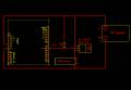
I am starting work on a project that will use a pot and an Arduino Uno to control the brightness of a 12v LED strip. Unfortunately I have no experience with this (yet) so I have no idea what I'm doing (yet). The LED strip is 3m of 5630 LEDs with a recommended current of 8A. I have a 12v 10A power supply in front of me.

I'm looking at this tutorial (http://itp.nyu.edu/physcomp/labs/mo...o-control-high-current-loads-with-an-arduino/) which says I need a transistor if I'm powering a motor, but not if I'm powering a lamp. All the other tutorials I found are for RGB strips whereas mine is just one color, thus this tutorial was the closest thing I could find.

So here's what I think I need to do, which may or may not be accurate:
Use the wall wart for the DC jack on the Arduino.
Splice a negative wire into the power supply and run that to the negative on the LED strip.
The positive from the LED strip connects to ???

So do I need a transistor or not?

As for wiring in the pot, I'm sure I can figure that out. I haven't researched it yet, though, because I'd like to just do one step at a time.
 

MikeML

Joined Oct 2, 2009
5,444
Are you going to use the PWMed AnalogWrite port pin on the Arduino to control the brightness of the LED strip?. If so, an NFET is the best way to pulse the LEDs.

Do the LEDs already have built-in current limiting?
 

GopherT

Joined Nov 23, 2012
8,009
You can use the barrel connector of the arduino and apply your 12v from the power supply. The on board voltage regulator connected to the barrel connector will convert your 12v to 5.

The output pin of the arduino goes to the base of the transistor. The emitter goes to ground. The collector goes to the cathode (K) of the LED that you are controlling. The LED anode connects to the current limiting resistor or constant current source (the current limiting is likely internal to the LED strip). The resistor connects to the 12v power supply rail.
 

Thread Starter

majhi

Joined Jul 2, 2014
55
Are you going to use the PWMed AnalogWrite port pin on the Arduino to control the brightness of the LED strip?. If so, an NFET is the best way to pulse the LEDs.

Do the LEDs already have built-in current limiting?
I'm assuming that I'll be using some sort of PWM, but like I said, I'm just starting with this stuff so I don't know what port pin in specific I'd need to use.

You can use the barrel connector of the arduino and apply your 12v from the power supply. The on board voltage regulator connected to the barrel connector will convert your 12v to 5.

The output pin of the arduino goes to the base of the transistor. The emitter goes to ground. The collector goes to the cathode (K) of the LED that you are controlling. The LED anode connects to the current limiting resistor or constant current source (the current limiting is likely internal to the LED strip). The resistor connects to the 12v power supply rail.
When you say that the emitter on the transistor goes to ground, do you mean the ground of my power supply or the ground pin of the Arduino? As for the LED anode, does that mean I need to splice in a positive wire (not negative like I had assumed), hook that to a resistor, and have that go to the LED strip? If I need a resistor at all, because from what I understand from your post, I could just hook it into the power supply if the current limiting portion is internal to the LED strip.

As for the transistor itself, I have a TIP31 laying around. Will that work or should I use a different kind?
 

MikeML

Joined Oct 2, 2009
5,444
Pictures are worth thousands of words:

Ard.gif

The 12V supply can also be used to power the Arduino (or not). Note that common ground connection between the Arduino and 12V supply must be there if the 12V supply powers the Arduino board or not! Note the polarity on the LED strip.

M1 is any "logic gate" NFET (NMOS). There are literally thousands available that would work in this application. If you pick one with an Ron of <12mΩ, at 8A load current, it will not need a heatsink. Attached is a list of suitable NFETs I got off DigiKey that would work in this application. It is a comma separated file that I had to rename to .txt

The lower circuit has a problem. The Darlington Q1-Q2 has a saturation voltage of ~2V. At 8A load current, Q1 will be dissipating 16W, which requires that it be bolted to a HUGE (PC CPU like) heatsink. You can use an integrated Darlington transistor like a TIP120, or make it out of a small-signal transistor like a 2n3904 driving a power transistor like your Tip31. In either case, you still need a big heatsink.
 

Attachments

Last edited:

Thread Starter

majhi

Joined Jul 2, 2014
55
Pictures are worth thousands of words:
Dude, you're awesome. Thank you so much for that! I was playing with ExpressPCB to come up with an idea, but this is even better (since you're much more knowledgeable than I am). So with the top circuit, am I to understand that I will cut off the existing barrel plug and wire it into the Vin and GND pins? Or can I still use the barrel plug, but splice in the junctions that I've circled here?

As for the NFET list you sent me (again, thank you), do I need one that's rated for 96W or higher (12V*8A) or does that not matter?

Sorry for all the newbie questions, I'm just getting my feet wet by jumping headfirst into a complicated project, haha.
 

Attachments

MikeML

Joined Oct 2, 2009
5,444
If you plan to use the external 12V supply to run the Arduino as well as the LED strip, then connect nothing to the 5V input to the Arduino board.

Cut and strip the wires on the barrel plug that mates with the jack on the Arduino. Connect the wire that goes to the center pin to +12V on the power supply. Connect the + end of the LED strip to +12V on the power supply.

Connect the wire that comes from the barrel of the Arduino plug to the 0V end of the supply. Connect the Source of the NFET to the 0V end of the power supply.

Connect a wire (#22 or bigger) from the Drain of the NFET to the -end of the LED strip.

Connect a wire from the Gate of the NFET to the desired port pin on the Arduino board.

No, the NFET needs to have a Vds rating >20V, an Ids current rating >10A, and a low on resistance. If you use the "logic-gate" variety, the Vt is <2V automatically.
 

MikeML

Joined Oct 2, 2009
5,444
Okay. So from that step-by-step and the image from earlier, this is what I've come up with. Is this correct?
I would do it as I described verbally earlier. I modified your layout. Note the blue connections. This way, the current path for the 8A LED Strip current does not flow along any of the red wires going to the Arduino. This is called a single-point grounding method, and helps prevent ground-loops.

lay.gif

There have been a lot of posts on here about: "I am using my PIC/Arduino to control a motor/relay/inductive load and my processor glitches unexpectedly". Most of the those issues are traceable to improper grounding, sharing high current wiring with signal wiring, and ground loops as described above. Now with an 8A resistive load (your LED strip), this is unlikely to have happened the way you routed the conductors, but I am making the point about keeping the high-current power wiring entirely separate from the wires going to the Arduino. Note that the blue wires touch the red wires only at the power supply terminals.

One other minor point. I would twist the red wire going to GND on the Arduino around the red wire going to Vin (twisted-pair). Keeping the blue conductors separate from the red ones would apply on a PCB layout, too.
 

Thread Starter

majhi

Joined Jul 2, 2014
55
Great, thanks! I updated my schematics accordingly. But because I'm a masochist and like to complicate my life more than I need to, I added a pot (10k, no clue what wattage) to the mix. I think it's pretty straightforward, judging by what I'm seeing online. Hopefully I'm at least close?

ard4.png
 
Top