Arduino based Water level controller - Problem in High voltage drop Between sensors inside tank

Thread Starter

snmjack

Joined Jun 1, 2016
9
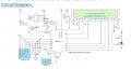
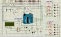
Hi, my name is swapnil. I am trying to make a water level controller using arduino. I refered many circuit ideas for different website and made my own design. Simulated it in Protues and it worked fine. Also i designed my PCB in eagle and started implementing.
Everything was going as per plan, but when i tried to test the input sensors voltage, i got major voltage drop due to water acting as resistance between the sensors.
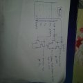
For sensor - I used a PVC pipe, in which Cat 6 LAN cable is inserted. One wire of LAN cable is connected at bottom of PVC pipe with a stainless steel metal. This wire is also connected to 5V supply through board. Same way other sensors are connected to different levels of PVC pipes. Now when water rises till 1/4 tank full sensor, arduino will get the voltage at its digital input pins (Because of water, 5V sensor and 1/4 tank full sensor will get short).
Now the problem here is, water is conductive but with high resistance since its not much salty, so instead of getting 5V at 1/4 tank full sensor, i am getting around 2-3 volts.
My board is also ready and sensor set for both Below tank and overhead tank are both ready, and my program also works fine. but i am stuck at this voltage drop problem.
I had one thing in mind, what if i use a intermidiate circuit betweent he sensor set and board, which will detect any voltage above 0V and give output 5V. But i am not getting any such circuit ideas to build one.

Anyone have any idea.. how to tackle this problem.
 

Attachments

djsfantasi

Joined Apr 11, 2010
9,156
I do not understand your dilemma. The Arduino should be able to detect any voltage above 0 and act accordingly. You have to treat the input pins as analog input instead of a digital one. Are you using the AnalogRead statement to read your pins?
 

Thread Starter

snmjack

Joined Jun 1, 2016
9
yes. you are correct. But as per my circuit.. i have connected sensors to digital input pins, since i needed 5 + 5 (bottom tank and overhead tank) sensor input. Also, when i read a bit on arduino digital I/O pins, somewhere it stated that... voltage below 3.3 volts will be treated at low input.
I am using digitalread statement with If else logic, where the code is comparing sensor voltage with 5v vcc for detecting water level.
 

djsfantasi

Joined Apr 11, 2010
9,156
But pins A0 through A5 ARE analog input pins, and they are what you show as what you are using, on your schematic.

Edit: I just noticed that you need ten analog inputs. Sorry
 

djsfantasi

Joined Apr 11, 2010
9,156
Crazy thought. Use two Arduinos, one reading the analog values for each tank. Then, designate one as s master and use digital pins or serial communications to communicate between the two.
 

Thread Starter

snmjack

Joined Jun 1, 2016
9
Alec_t @ - thanks, but please refer my protues image file, where i have used 220 ohm resistor in series of led which is directly connected to sensor, so when the water level is detected, sensor voltage will go to the digital input pins and also to the LED, so i can get visual indication of the levels. As per your suggestion, i should increase the resistance from 220 ohm to 100K, will the LED glow in this case?

djsfantasi@ - Analog input pins are utilised for I2C LCD and driving the motor. So had to go for digital pins as input.
 

Thread Starter

snmjack

Joined Jun 1, 2016
9
i think, adding one more arduino will complicate the design, u have any other ideas? any intermediate circuit to hold the sensor voltage to 5V, even if the voltage at sensor is below 5V.
 

Alec_t

Joined Sep 17, 2013
14,280
i have used 220 ohm resistor in series of led which is directly connected to sensor, so when the water level is detected, sensor voltage will go to the digital input pins and also to the LED, so i can get visual indication of the levels.
That's not going to work. The water resistance will be high and, since it would be in series with the LED, would result in a feeble LED current.
 

Thread Starter

snmjack

Joined Jun 1, 2016
9
so what do u suggest, increase the resistor value or any other change...
i have also attached my proteus and arduino files for your refernce
 

Attachments

ErnieM

Joined Apr 24, 2011
8,377
I have attached a image file of transistor logic for sensor... will this logic work?
I agree a buffer here will help you but I would use a CMOS hex inverter for that for the lowest current draw out of your sensor. Do not connect the LEDs directly to the sensor but to the output of the buffer... And perhaps a parallel buffer just for the led to keep the drive voltage high enough to drive the Arduino.

Way back we designed a water level sensor that consisted of two isolated metal probes, one solid indide a hollow tube. As liquid fills the tube the capacitance will change and thus you get a continuous reading of the level. To read the capacitance we converted it to a pulse wave using a good ole 555 (not my choice) with the probe as the oscillator cap. You need to calibrate this, and the cal changes with different liquids but it is a simple thing to do with the micro and some buttons.
 

crutschow

Joined Mar 14, 2008
34,285
I have attached a image file of transistor logic for sensor... will this logic work?
Not as drawn.
You have the second transistor base directly connected to the +5V so its output will be high all the time.

But you may be able to get by with just one transistor used as an emitter follower.
Connect its collector to +5V as you show and connect the LED with its series resistor from the emitter to ground.
Connect the transistor base directly to the water sensor electrode with no resistor.
Connect the Arduino input to the transistor emitter.

That will reduce the current required through the sensor by the Beta of the transistor.
The emitter output should then be about 4.3V when the sensor is submerged.

If necessary you could use two transistors in a Darlington configuration to further reduce the sensor current.
 

Thread Starter

snmjack

Joined Jun 1, 2016
9
okk.. so what i understood is.. i can use 2 HEX inverter say 4049, one goes to adruino and other to the LED.
One doubt i have.. say if the output of buffer is 5V... and it travels through the cat 6 cable from overhead tank to ground floor...(40-50 meter in length). the cable length will also drop some voltage... and if this voltage had dropped to say 3V till it reached arduino... will arduino detect it as high or low???... (sensor input is connected to digital pin ... configured as input). If this happenes... how to tackel it...??
 

Thread Starter

snmjack

Joined Jun 1, 2016
9
Not as drawn.
You have the second transistor base directly connected to the +5V so its output will be high all the time.

But you may be able to get by with just one transistor used as an emitter follower.
Connect its collector to +5V as you show and connect the LED with its series resistor from the emitter to ground.
Connect the transistor base directly to the water sensor electrode with no resistor.
Connect the Arduino input to the transistor emitter.

That will reduce the current required through the sensor by the Beta of the transistor.
The emitter output should then be about 4.3V when the sensor is submerged.

If necessary you could use two transistors in a Darlington configuration to further reduce the sensor current.

thx crutschow... i think .. ur suggestion would work. will try it out. i have 2n2222 transistor... would this work?? also how to calculate resistor value in series of transistor...? should it be high.. or low?
 

dannyf

Joined Sep 13, 2015
2,197
The 10k resistors are too much off a load for the equivalent resistance of the sensor.

I would first measure the sensors resistance. From there, pick a pull up or pull down resistor so that you have a clear transition of logic.

Let's say your sensor has a resistance of 500k. And you want active high. So a pull down resistance of 4x of that would approach the St pins input threshold (80 percent Vcc). I would go above that and pick a 5x or 6x multiplier.

I think those types of resistance. Will expose to a slew of issues. As such, inpendence translation near the sensors is the way to go.
 

crutschow

Joined Mar 14, 2008
34,285
thx crutschow... i think .. ur suggestion would work. will try it out. i have 2n2222 transistor... would this work?? also how to calculate resistor value in series of transistor...? should it be high.. or low?
A 2N2222 transistor is fine.

The resistor value is determined by the desired LED current.
Thus R = (4.3V-Vled)/Iled where Vled is the LED forward voltage drop, and Iled is the desired LED current.
 
Top