 Facebook
 Google
 GitHub
 Linkedin
Thanks, gentlemen.
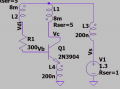
Edited, added : The genuine circuit is :

Unsure about the windings phasing. Cell is 1.3V.
Will build the circuit presented by Danko; which is somewhat similar and will report findings.
The resistances measured in the working transformer 0.5 ohm and 43.6 ohm corresponding to Xicon part number 42TU008. (Of course not available at Mouser)
Worth to try ordering for evaluation. Was $2; now $50+ in the robbery trend. [ Dimensionally, 42TL008 is nearest similar ]


Edited, added : The genuine circuit is :
Unsure about the windings phasing. Cell is 1.3V.
Will build the circuit presented by Danko; which is somewhat similar and will report findings.
The resistances measured in the working transformer 0.5 ohm and 43.6 ohm corresponding to Xicon part number 42TU008. (Of course not available at Mouser)
Worth to try ordering for evaluation. Was $2; now $50+ in the robbery trend. [ Dimensionally, 42TL008 is nearest similar ]
Attachments
-
 63.1 KB Views: 5
Last edited:


