Facebook
 Google
 GitHub
 Linkedin
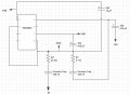
Hi, I try to know what this circuit is about
And how it work
I think it’s a circuit for audio amplification, it has a TDA2822 chip in it.
Mod: cleaned up your image.E

And how it work
I think it’s a circuit for audio amplification, it has a TDA2822 chip in it.
Mod: cleaned up your image.E
Last edited by a moderator: