Facebook
 Google
 GitHub
 Linkedin
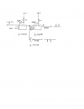
I need a circuit that has two inputs A and B. If A detects positive edge then regardless of what the B input is,
the output will be a high level of 5 volts.
On the otherhand, If B detects a positive edge then regardless of what the A input is, the output will be a
low level of 0 volts.
thanks
the output will be a high level of 5 volts.
On the otherhand, If B detects a positive edge then regardless of what the A input is, the output will be a
low level of 0 volts.
thanks
Attachments
-
 7.1 KB Views: 26