 Facebook
 Google
 GitHub
 Linkedin
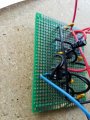
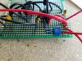
So, I am working on a project for which I need to use treadmill motors. Currently using a circuit that I found on http://el34world.com/Misc/Cnc/images/TerrysBoard2.gif I have made this circuit on breadboards twice now, and each time it has worked. I have built thew circuit on pcb 3x now and each one fails. I am beyond frustrated. I have tried both with and without the capacitors bridging + and ground and had success with a .47uF with breadboard while nothing has worked on PCB at all. Anyone who can find my error will be legend in my mind... \
I have attached my most recent attempt.
I have attached my most recent attempt.
Attachments
-
 524.1 KB Views: 34
 -
 566 KB Views: 31
 -
 661.6 KB Views: 32


