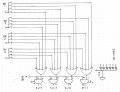
tracecom, with those nice words now I have to own up to a whopper mistake on OR gate wiring. Diodes are not wired directly to switch contacts, need a whole bunch of wire to inter connect them. Drew out 4 switches & 4 ORs to illustrate.
As a learning experience, might try both approaches, μC & hard wire?
I was thinking the same thing. Challange accecpted!
Bernard, I'll happily focus on a uC solution if you're game for the hard wire approach. I think this could be an excellent example to compare the two methods to give other members in the future an idea of what each method entails.
Dthx, as you can see, sometimes projects morph into more because, well, we find it challanging and fun. We're strange lot, I know . . .
If the μC can handle all of those inputs & outputs- WOW. Sometime I must take off a year and learn more about them. I believe it would be easier to operate pots if they were single turn with labeled times. Also ' would be more comfortable with diodes across solenoids & not rely on FET internal clamps. If power supply & FETs are rated for multiple simultaneous firings, might create some interesting effects. What a fun project!
A uC can do this, some better than others. I want to look into a shift register on either the input or output or both to reduce the I/O count.
The PICAXE isn't the greatest choice for speed or accurate timing applications on its own, hence the external clock.
I think this may be a great project to see what is involved with using a uC for your benefit as well.
Yes, we can use single-turn pots and feed them into an ADC input then tell the uC that between 0-0.5V represents 1 second, 0.5-1V represents 2 seconds and so on. I haven't done this yet, so I'm not 100% sure on the schematic I posted.
Diodes it is. I know diodes should be used across relays, motors, and solenoids, I just couldn't recall how they were supposed to be wired so I didn't include them in the schematic, but I will add them.
Thank you,Bernard...
Some of what you are saying is beyond me, at this point...
but yep, its gonna be fun to see it work.
Of course my fallback is to just have 6 toggle switches and have someone energize each solenoid and count in their head...for the time up and time down.....
But if you guys will help me, it would make the experience so much richer for the kids...they'll get to see how all this is done...pneumatics and electronics....and I will learn a lot too.....
It would be a boring world, my friendc, to stop learning....
D.
The race is on-@ - turtle speed. At least some parts are now on order. Using FDS 9435 P ch. SM FET, 5A, 30V for solenoid drivers so that one side of solenoid is ground. Power supply not included, 12V @ 2A. ' will be out of town most of next week.
OK....thanks, Bernard.
Im familiar with the turtle and the hare story....Turtle speed is good.
Hey, Elec_Mech....
I got your programmer,power supply, and interface cord in the mail today..
So...received....in good order.
When you guys work out a circuit and components....let me know....
Im ordering one pneumatic valve and a pneumamic cylinder...
"Air valve and and air cylinder"....
And will wait for instructions...
Im also going forward with the target support base and mechanics of the target pop up mechanism itself.
That doesnt concern you guys, electronically, though.
But I'll document it and be sure to keep a record of everything we do...so we can show everyone....
D.
Elec Mech..
I received the package today in good order.
Download cable, progrmmer board, and power adapter
All OK.
Am I to understand that I should use this to practice on my own to learn about what we are doing?
That would be great and if so...Im ready to dive in and ask question s along the way.
The chip retainer on the board has only 20 pin slots, however.
I know thats a lot...but ...you mentioned in an earlier post that I would need a 28x2 chip....and that would have 28 pins....
So this board you sent me is for my own use with a 20 pin chip, correct...?....something to learn on...?
D.
I'm working on reducing the pin count so you can ultimately use a smaller chip. The 28X2 is ten bucks!
Yes, you could still use the programmer to program the 28- or 40-pin PICAXEs either by using a few jumper wires from the 20-pin ZIF socket or by getting an old 9-pin serial cable or socket and using the cable directly.
I'll come up with a revised list of items to order from Aztecmcu.com and send it later. This will allow you to get started with the PICAXE while the rest of us work on our respective designs.
Im posting this here because it relates to my project and its been suggested that I keep those Q's in one place.
Ive been reading and some things are becoming familiar enough to generate a few questons in my mind.
I may have asked this question earlier but I cant find where I did...if so...I apologize.
If you look at a simple 555 monostable circuit....it seems that the resistor is upstream of the capacitor. ...(closer to Vcc)
Why isnt it the other way around....
I would think that the resistor would be last ....holding back voltage from the capacitor ....thereby creating a time delay.....
Can someone explain....?
Mr. Chips of Bernard...and I had a conversation about this, I believe...but I cant find it....or I may be mistaken...
D.
Back to cool Tucson,104 F vs 114 F in Phoenix.
Referring back to post # 22 or 24, timing R & C are in series. R limits current flow into C such that R X C voltage at junction is about 63% of VCC, [ one time constant ] as seen at pin 6 & 7. 555 comparator is biased at 2/3 of VCC so reset occurs almost at RC.
Switches & FETs arrived, so will start throwing them in a box.
Well, the resistor chokes the voltage before it gets to the capacitor....If you say so....but I still cant reason out why....
But, thats OK...at this point..Im still catching on to the big picture....
Question...Please look at your schematic on my #22 post...
what if I put the rotary swith on the left side of the circuit before the resistors and make those resistors adjustable....
Then when I select .....say.....position #2 on the rotary switch...that position would have its own time setting....
On time and off time would be the same...which is Ok at this point.
Would that work?
D.
Huh.!....solar power...you live in the right place for it....
to your point on the circuit...
Well, that would add another layer of competition to the targets...Keep everyone from getting bored and prevent the archers waiting their turn from scoping out the course and knowing how much time they had between shots...
But...it isnt a deal breaker.....it would be cool, though.....and if it doesnt take some "hard to come up with" circuitry or out of reach costs.......then I would be for it....
Dry heat makes a big difference. Was just in FL working outside for two days, one in the tropical storm (lots of rain anyway) and was as muggy as all can get out both days. Ugh.
What you'r suggesting sounds like having independent timing for each valve?
This isn't hard to add to a uC program, the real zigger is the user interface(UI) - how would you have the user enter in the times for all six targets? This is where an LCD would be handy. For now, I agree with Bernard that we stick with the original plan - same ON time for each target and same OFF time. You can always modify the circuit later once you get everything running.
An alternate idea for the uC option is to add a random switch - in one position you control the ON and OFF times for the targets, in the other position the uC comes up with a "random" number within some boundaries to turn on and off each target. This shouldn't be too hard to do and eliminates the need for a more complex UI. Again, let's stick with the original plan and I can help you add this after the fact.
I've found a nice I/O expander that communicates via I2C which should work well with the PICAXE, specifically the MCP23017. I'm studying the datasheet and online examples now as well as making a schematic. My current plan is to use a 20M2 which will provide plenty of additional pins for future add-ons.

 Facebook
 Google
 GitHub
 Linkedin