Another 555 timer question

Thread Starter

dthx

Joined May 2, 2013
195
Yep....I agree with sticking to the orig. plan...
Keep me posted...I feel like I should be doing more....but right now I cant...
I am learning more about the fourm, though .....how to post circuits, (attach images)....that should help when I have a Q ...and also as a learning too for mel. Im also going thru the Ebook videos....
We're gonna have fun with this project....
D.
 

Bernard

Joined Aug 7, 2008
5,784
That looks really neat, elec-mech. Quite a contrast with hard wire, 'almost needed a shoe horn to stuff all of the wires in the box- but they are all in and working. 'Used a P-ch FET so that one side of solenoid lines are at gnd. Left dial is UP, about 2 to 10 sec, & right dial in Down, 2-10 sec. dthx, thought you would want to label and calibrate. Used LEDs & small 12V motor on outputs to test. Was not enough room for manual over ride
 

Attachments

Thread Starter

dthx

Joined May 2, 2013
195
That's amazing to me that you guys can do this....
I cant do much right now...
Had my left hip replaced on Wednesday.
Just leaning back in my old big chair and able to type on my wireless keyboard.
I should be up and around by Wed of this coming week.
The pneumatic valve is here....but I havent done anything with it....
Thanks for what both of you have done....
Ill kep you posted on my progress too.
D.
 

Bernard

Joined Aug 7, 2008
5,784
dthx, if you still want option of random timing, thumb nail works fine on breadboard & only requires addition of OR gate @ U6-7 & a socket in big box, BB. Ckt. might fit in a small box,SB, which I have, 3.5 X 2.5 in. The number of times with 4022 is 8, with 4017, is 10, breadboard set up with only 6. I recorded some of the times, or 6 numbers representing the 6 different times from 2 sec to 10 sec. I do not see a pattern- lookspretty random.
1,5,2,4,1,3,4,1,1,2,5,2,1,4,1,4,3,2,1,2,1,4,3,4,2,5,6,3,4,6,2,1,6,4,5,3,5,3,1,1,4,4,5,1,5,5,3,
,4,5,3,6,4,6,1,1,2,4,5,4,3,4,6,5,5,3,1,1,6,4,1,3,6,4,6,5,2,4,1,3,4,1,1,5,3,6,1,2,6,

20-1 s; 10-2 s; 13- 3 s; 19- 4 s; 13- 5 s; & 11- 6 s
What do you think?
 

Attachments

Thread Starter

dthx

Joined May 2, 2013
195
today is the first day since my surgery that Ive felt like doing anything....so apologize for the delay.
What do I think?
I think you're a damn genius.
And..I'm envious of the personal satisfaction that you must get by being able to to do this for someone...
Many thanks again.
I still cant get around yet but I'll print your circuit out with your notes and go over it with someone who can help me put it together....He's waiting on me and you all are too.
Many thanks and I'll be in touch in a few days....
I cant wait to put it together.
D.
 

Thread Starter

dthx

Joined May 2, 2013
195
Hey Bernard....Ive been looking at your schematic....
1.) why are U10 thru U14 wired together?
2.) is the component between each solenoid and the 100k resistor a switch.... and is that switch put in there for manual operation when I throw SW 8 ?
I may have some more questions....
thanks
D.
 

Bernard

Joined Aug 7, 2008
5,784
Good morning, just a few min. before bowling time.
1. U9- U14 are NAND gates. If both inputs are HI , output is LO, signal that turns on the P ch FET. Gate R is 100 Ω, not 100k. The first cycle starts with U9-1, HI , as SW is in #1 position , the HI will appear AT U9-2 [ #2, looks like we have 2 U9.s], the other input-1 is output of UP timer, common to U9#2-U14. As each NOR gate is selected it will receive the same UP time. The " SW"s [electronic switch] are SM,surface mount, FET's, FDS 9435A, 5A @ 30V, RDS .05Ω.
SW8 is power on SW. Keep the questions coming & maybe I can figure this thing out.
 

Bernard

Joined Aug 7, 2008
5,784
I modified the ckt. a bit by adding a powerup reset & a plug to interface with the random time module. If you want the main timer, it is available for cost of parts, $ 36, + postage. Do you want any of the parts for the random timer? I need to redraw the ckt to correct & add.
 

elec_mech

Joined Nov 12, 2008
1,500
In the immortal words of Professor Hubert J. Farnsworth: "Good News Everyone!"

Okay, finally had some time to test some code. Learned I needed to add some pull-up resistors to the data lines for proper I2C communication. Also discovered, after a great deal of debugging :rolleyes:
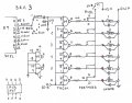
, that 32 diodes are needed to isolate the BCD signals from each other. Once I wired that up, I finally saw consistent, well rather expected, results from the I/O IC. Prior to that, they were consistently wrong. :eek:

Now I can work on the main code . . .

I'll try not to take so long to move along, just been really busy on the home front, so getting time to test and debug at home has been challenging.

Updated schematic attached. No guarantee it is final yet.
 

Attachments

Thread Starter

dthx

Joined May 2, 2013
195
Elect Mech....
Put this on the back burner for now and I'll get back to you when and if....
Our little 4H program had to sell its 3D targets ....so I have not targets to use for the PopUp project.
Small town blues...
D.
 

Thread Starter

dthx

Joined May 2, 2013
195
Well...I think this is the place to post this...
The 4H Shooting Sports Program in my little town now has a "board of directors".
They have voted not to continue the pop up archery project that I started.
When there was just one guy...me....I could do interesting things....
Unfortunately, I am not a member of the board anymore...
So...thanks to everyone that helped with this...but it's in the boneyard for now...
D.
 
Top