Analyses for bipolar junction transistor

Thread Starter

full

Joined May 3, 2014
225
Hello everyone

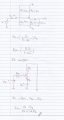
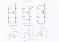
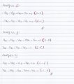
I do Analyses for bipolar junction transistor (BJT) PNP on A ,B & C .

for analysis A the current flow from emitter to base & collector .
for analysis B the current flow from emitter to base & collector but there is source in emitter .
for analysis C the current flow from emitter to base & collector but there is source in emitter .
please check my analytic true?
please If there is anything unclear told me.....

thanks
 

Attachments

Last edited:

Thread Starter

full

Joined May 3, 2014
225
update :

full4.PNG

analyses :

full5.PNG

I think there is wrong in analysis B in emitter to base (Vth) but I do analysis should they (vth ) in positive not in negative .

and there is wrong in analysis C in emitter to base (-Vre & -Vth) same problem in analysis B .

I think there are problem in my loops :confused:

thanks :)
 

MrChips

Joined Oct 2, 2009
34,627
Don't let the change of polarity confuse you. All three circuits have the same configuration and hence the analysis is the same.
The analysis is still the same for a NPN transistor.
 

Jony130

Joined Feb 17, 2009
5,593
Why you cannot stick to one convention when doing KVL ?
For case A
-VRe - Vbe - VRth + Vth = 0
-VRe - Vec - VRc + Vcc = 0
Also notice that case B and C are identical (Case B is turned 180 degrees case C). So KVL also must look identical.
Also you made a error in case B, why Vth is negative ??

Also notice that the only difference between case A and B&C is reference point (GND).
So the current will stay the same but the voltage will change.
Try analyze this circuit very careful.
3.PNG
And for example do you understand why the base voltage is -1.6V in case A and 7.4V in case B ?
 
Last edited:

Thread Starter

full

Joined May 3, 2014
225
Why you cannot stick to one convention when doing KVL ?
For case A
-VRe - Vbe - VRth + Vth = 0
-VRe - Vec - VRc + Vcc = 0
Also notice that case B and C are identical (Case B is turned 180 degrees case C). So KVL also must look identical.
Also you made a error in case B, why Vth is negative ??

Also notice that the only difference between case A and B&C is reference point (GND).
So the current will stay the same but the voltage will change.
Try analyze this circuit very careful.
View attachment 74720
And for example do you understand why the base voltage is -1.6V in case A and 7.4V in case B ?
3.PNG

for first circuit :

Vee -Vre + Vbe - Vth - Vth

second circuit:

Vee -Vre + Vbe - Vth - Vth

the first circuit and second is same
And for example do you understand why the base voltage is -1.6V in case A and 7.4V in case B ?
no
sorry for late because I have exams
thanks
 

Jony130

Joined Feb 17, 2009
5,593
I have another circuit :

me Vth and DC analysis true?
Very good, but why you drew your circuit upside down ?
View attachment 74799
the first circuit and second is same
And for example do you understand why the base voltage is -1.6V in case A and 7.4V in case B ?
no
First you need to understand what GND is, so please read this
http://forum.allaboutcircuits.com/threads/ground-node.102921/
Once you understand what GND is. Pleas notice where GND is in the first circuit. Ground is at positive battery terminal.
And because the voltage at base is measured with respect to ground, this voltage is equal to the voltage drop across R2 resistor with minus sign.
But if our ground is negative terminal then voltage at base is equal to VR1 voltage drop.
On the other hand the collector voltage for the first circuit is a sum of a voltages Vc = VRe + Vce. But in second circuit Vc is simply -VRc.
Ve for the first circuit is -VRe but for second circuit Ve = VRc + Vce
And this is why this voltages are shifted by 9V depends on where the GND is.
VB = 7.4V but if we change the ground the base voltage will be shift down to 7.4V - 9V = -1.6V
 
Last edited:

Jony130

Joined Feb 17, 2009
5,593
If Av is a voltage gain for CE amplifier, the gain is negative but usually we ignore this "minus" sign. Because this only informs us about 180 degree phase shift.
 

Thread Starter

full

Joined May 3, 2014
225
If Av is a voltage gain for CE amplifier, the gain is negative but usually we ignore this "minus" sign. Because this only informs us about 180 degree phase shift.
If do not put "minus" on Av a voltage gain ,is mean wrong?
actually when did exam test , didn't put minus on Av

thanks
 
Top