Analog to digital converter atmega 8

Thread Starter

mah

Joined Mar 15, 2010
393
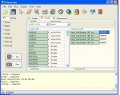
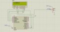
what is worng with this code. ? it is working in proteus but doesn't respond in real chip. i use 8 Mhz crystal
C:
/*******************************************************
This program was created by the
CodeWizardAVR V3.12 Advanced
Automatic Program Generator
© Copyright 1998-2014 Pavel Haiduc, HP InfoTech s.r.l.
[URL]http://www.hpinfotech.com[/URL]

Project :
Version :
Date    : 31/01/2018
Author  :
Company :
Comments:


Chip type               : ATmega8
Program type            : Application
AVR Core Clock frequency: 8.000000 MHz
Memory model            : Small
External RAM size       : 0
Data Stack size         : 256
*******************************************************/

#include <mega8.h>

#include <delay.h>

// Declare your global variables here

// Voltage Reference: AREF pin
#define ADC_VREF_TYPE ((0<<REFS1) | (0<<REFS0) | (0<<ADLAR))
float adc; int currentValue;

// Read the AD conversion result
unsigned int read_adc(unsigned char adc_input)
{
ADMUX=adc_input | ADC_VREF_TYPE;
// Delay needed for the stabilization of the ADC input voltage
delay_us(10);
// Start the AD conversion
ADCSRA|=(1<<ADSC);
// Wait for the AD conversion to complete
while ((ADCSRA & (1<<ADIF))==0);
ADCSRA|=(1<<ADIF);
return ADCW;
}

void main(void)
{
// Declare your local variables here

// Input/Output Ports initialization
// Port B initialization
// Function: Bit7=In Bit6=In Bit5=Out Bit4=Out Bit3=Out Bit2=Out Bit1=Out Bit0=Out
DDRB=(0<<DDB7) | (0<<DDB6) | (1<<DDB5) | (1<<DDB4) | (1<<DDB3) | (1<<DDB2) | (1<<DDB1) | (1<<DDB0);
// State: Bit7=T Bit6=T Bit5=0 Bit4=0 Bit3=0 Bit2=0 Bit1=0 Bit0=0
PORTB=(0<<PORTB7) | (0<<PORTB6) | (0<<PORTB5) | (0<<PORTB4) | (0<<PORTB3) | (0<<PORTB2) | (0<<PORTB1) | (0<<PORTB0);

// Port C initialization
// Function: Bit6=In Bit5=In Bit4=In Bit3=In Bit2=In Bit1=In Bit0=In
DDRC=(0<<DDC6) | (0<<DDC5) | (0<<DDC4) | (0<<DDC3) | (0<<DDC2) | (0<<DDC1) | (0<<DDC0);
// State: Bit6=T Bit5=T Bit4=T Bit3=T Bit2=T Bit1=T Bit0=T
PORTC=(0<<PORTC6) | (0<<PORTC5) | (0<<PORTC4) | (0<<PORTC3) | (0<<PORTC2) | (0<<PORTC1) | (0<<PORTC0);

// Port D initialization
// Function: Bit7=In Bit6=In Bit5=In Bit4=In Bit3=In Bit2=In Bit1=In Bit0=In
DDRD=(0<<DDD7) | (0<<DDD6) | (0<<DDD5) | (0<<DDD4) | (0<<DDD3) | (0<<DDD2) | (0<<DDD1) | (0<<DDD0);
// State: Bit7=T Bit6=T Bit5=T Bit4=T Bit3=T Bit2=T Bit1=T Bit0=T
PORTD=(0<<PORTD7) | (0<<PORTD6) | (0<<PORTD5) | (0<<PORTD4) | (0<<PORTD3) | (0<<PORTD2) | (0<<PORTD1) | (0<<PORTD0);

// Timer/Counter 0 initialization
// Clock source: System Clock
// Clock value: Timer 0 Stopped
TCCR0=(0<<CS02) | (0<<CS01) | (0<<CS00);
TCNT0=0x00;

// Timer/Counter 1 initialization
// Clock source: System Clock
// Clock value: Timer1 Stopped
// Mode: Normal top=0xFFFF
// OC1A output: Disconnected
// OC1B output: Disconnected
// Noise Canceler: Off
// Input Capture on Falling Edge
// Timer1 Overflow Interrupt: Off
// Input Capture Interrupt: Off
// Compare A Match Interrupt: Off
// Compare B Match Interrupt: Off
TCCR1A=(0<<COM1A1) | (0<<COM1A0) | (0<<COM1B1) | (0<<COM1B0) | (0<<WGM11) | (0<<WGM10);
TCCR1B=(0<<ICNC1) | (0<<ICES1) | (0<<WGM13) | (0<<WGM12) | (0<<CS12) | (0<<CS11) | (0<<CS10);
TCNT1H=0x00;
TCNT1L=0x00;
ICR1H=0x00;
ICR1L=0x00;
OCR1AH=0x00;
OCR1AL=0x00;
OCR1BH=0x00;
OCR1BL=0x00;

// Timer/Counter 2 initialization
// Clock source: System Clock
// Clock value: Timer2 Stopped
// Mode: Normal top=0xFF
// OC2 output: Disconnected
ASSR=0<<AS2;
TCCR2=(0<<PWM2) | (0<<COM21) | (0<<COM20) | (0<<CTC2) | (0<<CS22) | (0<<CS21) | (0<<CS20);
TCNT2=0x00;
OCR2=0x00;

// Timer(s)/Counter(s) Interrupt(s) initialization
TIMSK=(0<<OCIE2) | (0<<TOIE2) | (0<<TICIE1) | (0<<OCIE1A) | (0<<OCIE1B) | (0<<TOIE1) | (0<<TOIE0);

// External Interrupt(s) initialization
// INT0: Off
// INT1: Off
MCUCR=(0<<ISC11) | (0<<ISC10) | (0<<ISC01) | (0<<ISC00);

// USART initialization
// USART disabled
UCSRB=(0<<RXCIE) | (0<<TXCIE) | (0<<UDRIE) | (0<<RXEN) | (0<<TXEN) | (0<<UCSZ2) | (0<<RXB8) | (0<<TXB8);

// Analog Comparator initialization
// Analog Comparator: Off
// The Analog Comparator's positive input is
// connected to the AIN0 pin
// The Analog Comparator's negative input is
// connected to the AIN1 pin
ACSR=(1<<ACD) | (0<<ACBG) | (0<<ACO) | (0<<ACI) | (0<<ACIE) | (0<<ACIC) | (0<<ACIS1) | (0<<ACIS0);

// ADC initialization
// ADC Clock frequency: 250.000 kHz
// ADC Voltage Reference: AREF pin
ADMUX=ADC_VREF_TYPE;
ADCSRA=(1<<ADEN) | (0<<ADSC) | (0<<ADFR) | (0<<ADIF) | (0<<ADIE) | (0<<ADPS2) | (0<<ADPS1) | (0<<ADPS0);
SFIOR=(0<<ACME);

// SPI initialization
// SPI disabled
SPCR=(0<<SPIE) | (0<<SPE) | (0<<DORD) | (0<<MSTR) | (0<<CPOL) | (0<<CPHA) | (0<<SPR1) | (0<<SPR0);

// TWI initialization
// TWI disabled
TWCR=(0<<TWEA) | (0<<TWSTA) | (0<<TWSTO) | (0<<TWEN) | (0<<TWIE);

while (1)
      {
  currentValue= read_adc(0) ;
  adc=currentValue/204.6;

    PORTB=ADCW;
      }
}
Mod edit: code tags
 

Attachments

Last edited by a moderator:

Thread Starter

mah

Joined Mar 15, 2010
393
it is working with internal oscillator but when i select external 8 Mhz oscillator it doesn't work
 

JohnInTX

Joined Jun 26, 2012
4,787
Your schematic does not show that you have an external oscillator. Nothing is hooked to the OSC1 and OSC2 pins on the microcontroller.
 
Last edited:

BobaMosfet

Joined Jul 1, 2009
2,113
Your code is way more complicated than it needs to be.

1. Set your ADC pin for input.
2. Set your ADMUX channel & initialize it:
- set the ADC prescaler so it's running at a sufficient frequency
- fire off a single conversion simply to 'warm it up'
3. Go Read a value from the ADC for the value you want:
- wait for any pending conversions to finish
- fire a fresh conversion & wait for it
- grab the value

That's it. If you change channels, you have to do it all over again after each channel change. Otherwise, the first 2 steps above only need done once.

And again, you're using way too much code to do this. You should be able to do the above steps for the ADC in < 10 lines of C code.,
 

Thread Starter

mah

Joined Mar 15, 2010
393
Your code is way more complicated than it needs to be.

1. Set your ADC pin for input.
2. Set your ADMUX channel & initialize it:
- set the ADC prescaler so it's running at a sufficient frequency
- fire off a single conversion simply to 'warm it up'
3. Go Read a value from the ADC for the value you want:
- wait for any pending conversions to finish
- fire a fresh conversion & wait for it
- grab the value

That's it. If you change channels, you have to do it all over again after each channel change. Otherwise, the first 2 steps above only need done once.

And again, you're using way too much code to do this. You should be able to do the above steps for the ADC in < 10 lines of C code.,
ok,it is working. the problem is in setting fuse bits with external crystal
 
Last edited:

Thread Starter

mah

Joined Mar 15, 2010
393
Iam trying to use ADC of atmega 8 with external 8 MHz oscillator. the adc result is sent to PORTB and i tested it using led. now i want to compare the result to toggle led on portb but it doesn't toggle.It's working in simulation but doesn't in real hardware

I change ADC using potentiometer on channel 0.

C:
/*******************************************************
Chip type : ATmega8
Program type : Application
AVR Core Clock frequency: 8.000000 MHz
Memory model : Small
External RAM size : 0
Data Stack size : 256
*******************************************************/

#include <mega8.h>
#include <stdlib.h>
#include <stdio.h>
#include <delay.h>
#include <alcd.h>

// Declare your global variables here

// Voltage Reference: AREF pin
#define ADC_VREF_TYPE ((0<<REFS1) | (0<<REFS0) | (0<<ADLAR))
float adc; int currentValue;
// char str[16]; //allocate on lcd

// Read the AD conversion result
unsigned int read_adc(unsigned char adc_input)
{
ADMUX=adc_input | ADC_VREF_TYPE;
// Delay needed for the stabilization of the ADC input voltage
delay_us(10);
// Start the AD conversion
ADCSRA|=(1<<ADSC);
// Wait for the AD conversion to complete
while ((ADCSRA & (1<<ADIF))==0);
ADCSRA|=(1<<ADIF);
return ADCW;
}

void main(void)
{
// Declare your local variables here

// Input/Output Ports initialization
// Port B initialization
// Function: Bit7=In Bit6=In Bit5=Out Bit4=Out Bit3=Out Bit2=Out Bit1=Out Bit0=Out
DDRB=(0<<DDB7) | (0<<DDB6) | (1<<DDB5) | (1<<DDB4) | (1<<DDB3) | (1<<DDB2) | (1<<DDB1) | (1<<DDB0);
// State: Bit7=T Bit6=T Bit5=0 Bit4=0 Bit3=0 Bit2=0 Bit1=0 Bit0=0
PORTB=(0<<PORTB7) | (0<<PORTB6) | (0<<PORTB5) | (0<<PORTB4) | (0<<PORTB3) | (0<<PORTB2) | (0<<PORTB1) | (0<<PORTB0);

// Port C initialization
// Function: Bit6=In Bit5=In Bit4=In Bit3=In Bit2=In Bit1=In Bit0=In
DDRC=(0<<DDC6) | (0<<DDC5) | (0<<DDC4) | (0<<DDC3) | (0<<DDC2) | (0<<DDC1) | (0<<DDC0);
// State: Bit6=T Bit5=T Bit4=T Bit3=T Bit2=T Bit1=T Bit0=T
PORTC=(0<<PORTC6) | (0<<PORTC5) | (0<<PORTC4) | (0<<PORTC3) | (0<<PORTC2) | (0<<PORTC1) | (0<<PORTC0);

// Port D initialization
// Function: Bit7=In Bit6=In Bit5=In Bit4=In Bit3=In Bit2=In Bit1=In Bit0=In
DDRD=(0<<DDD7) | (0<<DDD6) | (0<<DDD5) | (0<<DDD4) | (0<<DDD3) | (0<<DDD2) | (0<<DDD1) | (0<<DDD0);
// State: Bit7=T Bit6=T Bit5=T Bit4=T Bit3=T Bit2=T Bit1=T Bit0=T
PORTD=(0<<PORTD7) | (0<<PORTD6) | (0<<PORTD5) | (0<<PORTD4) | (0<<PORTD3) | (0<<PORTD2) | (0<<PORTD1) | (0<<PORTD0);

// Analog Comparator initialization
// Analog Comparator: Off
// The Analog Comparator's positive input is
// connected to the AIN0 pin
// The Analog Comparator's negative input is
// connected to the AIN1 pin
ACSR=(1<<ACD) | (0<<ACBG) | (0<<ACO) | (0<<ACI) | (0<<ACIE) | (0<<ACIC) | (0<<ACIS1) | (0<<ACIS0);

// ADC initialization
// ADC Clock frequency: 62.5 kHz
// ADC Voltage Reference: AREF pin
ADMUX=ADC_VREF_TYPE;
ADCSRA=(1<<ADEN) | (0<<ADSC) | (0<<ADFR) | (0<<ADIF) | (0<<ADIE) | (1<<ADPS2) | (1<<ADPS1) | (1<<ADPS0);

lcd_init(16);
lcd_clear();

while (1)
{
currentValue= read_adc(0) ;
adc=currentValue/204.6; //(Arerf connected to 5 v )
if ( adc >=2.5 )
{
PORTB.1=0; // turn heater off
}

else
{

PORTB.1=1 ;// turn heater on
}

}
}
Moderators note: Please use code tags for pieces of code
 
Last edited by a moderator:

DickCappels

Joined Aug 21, 2008
10,187
The part about CLK/8 was an error on my part. That option does not exist on the ATMEGA8.

It looks like you have the clock set to use a 400 kH to 900 kHz crystal.

Suggest you try using CLKSEL3..1 set to 111 and also set CLKOPT to 1 to get sufficient drive to the crystal.

upload_2018-2-1_18-16-58.png
 

Thread Starter

mah

Joined Mar 15, 2010
393
I DID that. CLKSEL3..1 set to 111 and also set CLKOPT to 1 . still doesn't work
 
Last edited:

DickCappels

Joined Aug 21, 2008
10,187
From here it looks like you did all the right things, but it is still not working.

Can you tell whether the controller is running at all? A good way to check is to have code that toggles an I/O pin which you can observe with a scope on a DVM.

Checking the crystal pins with a scope should show that oscillation at 8 MHz is present. Lacking a scope, you can measure with a DVM -neither pin should be stuck against ground or Vcc.

Also be sure you using decoupling capacitors on the power supply. A 10k pull-up resistor on the reset pin is a good idea in noisy environments.
 

Thread Starter

mah

Joined Mar 15, 2010
393
Ok,I will check the oscillator using oscilloscope. But i want you to assure that the code has nothing wrong.
I already have results of (ADCW ) i sent it to portb and the led lite, so why the if condition doesn't respond ?
 

DickCappels

Joined Aug 21, 2008
10,187
[QUOTE="mah, post: 1231053, member: 78675" (some text removed for clarity) But i want you to assure that the code has nothing wrong.
I already have results of (ADCW ) i sent it to portb and the led lite, so why the if condition doesn't respond ?[/QUOTE]

C:
/
while (1)
{
currentValue= read_adc(0) ;
adc=currentValue/204.6; //(Arerf connected to 5 v )
if ( adc >=2.5 )
{
PORTB.1=0; // turn heater off
}

else
{

PORTB.1=1 ;// turn heater on
}

}
I don't know. Did you try running this code using constants in place of currentValue= read_adc(0) ; just as a check?

Note: I cannot assure that there is noting wrong with your code -I haven't used C during the past 10 years. I leave that task to somebody who is competent to do so.
 

be80be

Joined Jul 5, 2008
2,072
1 CKOPT
0100 CKSEL3…0
8.0MHz
Yours is not right you mess up and you brick your avr
I DID that. CLKSEL3..1 set to 111 and also set CLKOPT to 1 . still doesn't work

This maybe help you out
Code:
    // the MUX5 bit of ADCSRB selects whether we're reading from channels
    // 0 to 7 (MUX5 low) or 8 to 15 (MUX5 high).
ADCSRB = (ADCSRB & ~(1 << MUX5)) | (((pin >> 3) & 0x01) << MUX5);
ADMUX = (analog_reference << 6) | (pin & 0x07);
#if defined(ADCSRA) && defined(ADCL)
    // start the conversion
    sbi(ADCSRA, ADSC);

    // ADSC is cleared when the conversion finishes
    while (bit_is_set(ADCSRA, ADSC));

    // we have to read ADCL first; doing so locks both ADCL
    // and ADCH until ADCH is read.  reading ADCL second would
    // cause the results of each conversion to be discarded,
    // as ADCL and ADCH would be locked when it completed.
    low  = ADCL;
    high = ADCH;
#else
    // we dont have an ADC, return 0
    low  = 0;
    high = 0;
#endif

    // combine the two bytes
    return (high << 8) | low;
}
 
Last edited:

BobaMosfet

Joined Jul 1, 2009
2,113
In the ATMEGA8 datasheet, page 27, Table 4, it clearly shows that if you have an 8MHz oscillator crystal, you should set fuses as follows:

CKOPT = 1
CKSEL3-1 = 111

You need capacitors on your crystal, I suggest using the 22pF values suggested in the same table.

You should also set (in Table 5, the next page, next table) that startup time so the crystal is given time to start and stabilize, at:

CKSEL0 = 1
SUT1..0 = 11

This gives the crystal 65ms to start up.

Not saying this fixes your problem, but it answers your crystal configuration questions.
 

Thread Starter

mah

Joined Mar 15, 2010
393
I mentioned in post #10 that i did all this configuration, there is output if i send (ADCW TO PORTB) the led lites. but when i compare the adc in if condition it didn't give result
 

DickCappels

Joined Aug 21, 2008
10,187
(Some text removed for clarity) There is output if i send (ADCW TO PORTB) the led lites.
Are the LEDs arranged as one LED per bit o PORTB and do the binary values displayed on the LEDs seem to correspond to the voltage from the pot being fed to the ADC input?

If so, this is proof that the controller is running and that the ADC is working, so the failure must be in the comparison or the output of the bit to light the LED.

Which leads me to ask whether the syntax for these two instructions is correct.
PORTB.1=0; // turn heater off
PORTB.1=1 ;// turn heater on​
 
Top