I must design it with electronic circuits and I am unable to figure it how because the substrate here is glass and embedding chips is not possible...
So I need to make use of circuits to build a digital filter
IMHO you are wasting your time with a digital filter after the conversion. If you knew what you were doing, you'd have an analog front-end filter before the conversion.
Maybe he has a chip fabrication process that uses glass as a substrate. I think(?) what he said is that he cannot embed existing dice on the glass substrate.
Maybe he has a chip fabrication process that uses glass as a substrate. I think(?) what he said is that he cannot embed existing dice on the glass substrate.
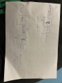
A 1st order IIR filter can be from a D-type latch, a multiplier and an adder. If you restrict your coefficients to negative powers of two, the multiplier can be replaced by a barrel-shifer.
A 1st order IIR filter can be from a D-type latch, a multiplier and an adder. If you restrict your coefficients to negative powers of two, the multiplier can be replaced by a barrel-shifer.
Could you please support me with a block diagram or circuit diagram on how this is connected or is it connected like D-latch ->multiplier -> adder in series.
This is a useful calculator: https://www.earlevel.com/main/2013/10/13/biquad-calculator-v2/
The simplest filter you can make is by selecting "one pole lp" from the list.
If you choose the frequency such that b1 = -1/(2^n) then all the multiplications can be done with a barrel-shifter.
 Facebook
 Google
 GitHub
 Linkedin
 1.8 MB Views: 12


