Facebook
 Google
 GitHub
 Linkedin
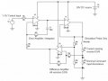
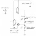
In the following link is a circuit from this site that I have used to take a 0-5 volt signal and convert it to a 4-20ma loop. I have tested the output with 470 ohm resistors and used an o-scope to get a voltage across it to verify that the conversion works which it does.
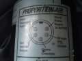
The problem lies in the pin out of the proportion air controller that I am using. The pin out on the datasheet is incorrect in that pin 5 and pin 2 are not the current loop pins as seen in the datasheet below. I have proved this with a simple ohm meter and found that the pin out is pins 1 and 3 as proven by a picture on the unit itself.
http://www.allaboutcircuits.com/vol_3/chpt_8/7.html
http://www.proportionair.com/media/brbb1.pdf
The pin out which I have taken a picture of and attached is as follows...
1. White command signal
2. Red analog output (ignore)
3. Green common
4. Orange TTL output (ignore)
5. Black power supply 15-24VDC
The problem lies in the fact that there is not two pins for the power supply ground and the 4-20ma loop itself. In the voltage to current circuit, there is a 250 ohm resistor that is between the current source and ground.
So what I'm left with is an incorrect ground for the power supply.
I hope I haven't been too confusing over the explanation. Any help would be greatly appreciated! Thanks!
Attachments
-
 162.7 KB Views: 24