Facebook
 Google
 GitHub
 Linkedin
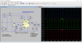
I have one on a solderless breadboard and it works as I expect switching LEDs back and forth.
However I have some questions: for starters what is the purpose of pin 5 the VL pin?
http://www.vishay.com/docs/70051/dg417.pdf
However I have some questions: for starters what is the purpose of pin 5 the VL pin?
http://www.vishay.com/docs/70051/dg417.pdf