Analog Switch - ADG5206 and CD4067B

Thread Starter

Z'YonG

Joined Feb 2, 2017
63
Hi,
I am having some problems about using ADG5206 and CD4067B. I am using ADG5206 to deal with a 36.8V signal, and CD4067B for another low voltage signal.

----------------------------------------------------------------------------------------------------------------------------------------------------------------
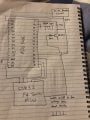
Here is the pins of the ADG5206:
upload_2017-8-7_11-43-0.png

I have made the following connections:
36.8V DC voltage to VDD and EN,
VSS and GND to ground,
36.8V DC voltage signal to D.

However, when I connect 36.8V signal to the D, the DC voltage drop to about half straight away. I don't know why and wondering if anyone can help. Here are the picture from oscilloscope before and after I connect the 36.8V signal to D:
Before:
upload_2017-8-7_11-48-23.png
After:
upload_2017-8-7_11-49-1.png

--------------------------------------------------------------------------------------------------------------------------------------------------------------

Here is the pins of CD4067:
upload_2017-8-7_11-50-57.png

I did the following connections:
VDD to 6V DC voltage,
VSS and INHIBIT to ground,
a low voltage signal to COMMON OUT/IN.

However, when I test the output signal from the 16 switches, all of them has contain noise, the signal changes a little be.
I am wondering if there is any way that can reduce that noise? such as connect resistor or capacitors...

Thank you for any help in advance!


RichardO

Joined May 4, 2013
2,270
Without complete schematics of your circuits (with component values) it will be almost impossible to answer your questions.

More details on your input signals is needed. What loads are you putting on the outputs?

Pictures of how you actually built the circuits would also be very helpful.
 

Thread Starter

Z'YonG

Joined Feb 2, 2017
63
Without complete schematics of your circuits (with component values) it will be almost impossible to answer your questions.

More details on your input signals is needed. What loads are you putting on the outputs?

Pictures of how you actually built the circuits would also be very helpful.

Hi, sorry I don't have the circuit with me at the moment, but I have drawn out the schematic:
For the ADG5206:

I have generated voltage peaks by turn one of the MCU pin on and off, and then I connected this signal to a transistor (BD547) through 680 ohms resistor, and use a 36.8V DC voltage that I generated from a dc-dc booster circuit to amplify the signal. I have set up the circuit like above, however, before I connect my signal to Pin D, it is -36.8V voltage peaks, but as soon as I connect it to Pin D, it is only around 16V. I have attached both pictures from oscilloscope in my post. I haven't connected any other load to the circuit yet, I am just using the oscilloscope to check the signals.

----------------------------------------------------------------------------------------------------------------------------------------------------------------------

For CD4067:


The signal that I sent to switch 10 is a reflection signal from an ultrasonic transducer, then I used STM32F4 MCU to switch S10 on, the signal that I got from the I/O pin has contain a lot of the noise, I haven't connect anything else to this circuit as well.

Thank you.
 

Thread Starter

Z'YonG

Joined Feb 2, 2017
63
Why you connected the D to the 36.8V with a 100uF?
Sorry, that was a mistake, it should be 100nF. It is a coupling capacitor that has been added to block the DC component that would otherwise be present at the output and across the transducer, and it is sized in order to introduce a high impedance to low frequencies, but not to the switching frequency.
The formular that I used is:
Xc=1/(2*pi*f*C),
 

ScottWang

Joined Aug 23, 2012
7,398
And another question, why the c of BD547 connected to 36.8V, when the BD547 is turn on then the 36.8V will be grounded, that is 36.8V shorted to ground.

You said that the noise came from I/O pin then you should make sure does the noise came from CD4067 or the ultrasonic transducer.
 

Thread Starter

Z'YonG

Joined Feb 2, 2017
63
And another question, why the c of BD547 connected to 36.8V, when the BD547 is turn on then the 36.8V will be grounded, that is 36.8V shorted to ground.

You said that the noise came from I/O pin then you should make sure does the noise came from CD4067 or the ultrasonic transducer.
We have tried different BC547 (my mistake, not BD547) circuit, but only connect like this will give us the high voltage peak. If you have other suggestions, I'd love to try it.

I have tested the signals from Ultrasonic transducer before and after I connect it to the CD4067, there is noise from ultrasonic transducer, but after the CD4067, there are more noise exist.
 

ebeowulf17

Joined Aug 12, 2014
3,307
I'm no expert, but I enjoy brainstorming around interesting problems. I've got a few ideas:

1) I agree with ScottWang that shorting your power supply at each pulse is an awful idea. Couldn't you replace the connection from your supply to the transistor/capacitor junction (the short horizontal line on your schematic) with a resistor, sized such that the current through the resistor when the transistor is active will be reasonably low, and the time to recharge the cap after each pulse will be reasonably fast? I believe 1k there would limit what is now a short circuit to 36mA while the transistor is active, but still recharge cap in 0.5ms (please double check my math on all this!) You should still get a near vertical negative pulse leading edge, although I suppose the trailing edge as it climbs back towards zero would be less crisp. I'd also recommend decoupling caps at the supply connections to each chip (hopefully you already have them and just didn't show them in sketches.)

1b) As a completely different solution to the short circuit issue, perhaps you could build a totem pole driver that connects supply voltage to the cap to charge it, and connects ground to cap to discharge it, but never connects supply directly to ground?

2) Add a pull up resistor to bias the d input up to your supply voltage so that your negative pulses can cover the full 36.8V range without going negative. It looks like the AG5206 doesn't want to see input voltages below its Vss voltage.
 

ScottWang

Joined Aug 23, 2012
7,398
If you want to send the signal from uC(STM32) to ADG5206 then you can modify it as the attached circuit shown with yellow frame, and the 680Ω change to 4.7K.

ADG5206_ZYonG.jpg

I have tested the signals from Ultrasonic transducer before and after I connect it to the CD4067, there is noise from ultrasonic transducer, but after the CD4067, there are more noise exist.
You can add a RC Integral circuit between Ultrasonic transducer and CD4067 to try, you can try the RC values from smaller as 10K, 470P, the best is to measures the frequency of noise if the noise can be identify.
 

ScottWang

Joined Aug 23, 2012
7,398
before I connect my signal to Pin D, it is -36.8V voltage peaks, but as soon as I connect it to Pin D, it is only around 16V.
Why was the voltage from 36.8V became 16V?

Because when a DC became a square wave (pwm) the output voltage will be like as:
Vout = Vin * duty cycle%
16V = 36.8V * duty cycle%
duty cycle% = 16V/36.8V = 43.478%

So
Vout = Vin * duty cycle%
Vout = 36.8V * 43.478% = 1599.99V

You can also calculate like this:
Vout = 36.8V * 43.5% = 16.008V
When you using the multi-meter to measure it then you will get about 16V.
 

Thread Starter

Z'YonG

Joined Feb 2, 2017
63
If you want to send the signal from uC(STM32) to ADG5206 then you can modify it as the attached circuit shown with yellow frame, and the 680Ω change to 4.7K.

View attachment 132621

You can add a RC Integral circuit between Ultrasonic transducer and CD4067 to try, you can try the RC values from smaller as 10K, 470P, the best is measures the frequency of noise if the noise can be identify.
For ADG5206:
Thanks ScottWang! I changed my ADG5206 circuit to your suggestion, and it actually works now. I am able to get my 36.8V signal out of the ADG5206 now! Really appreciate!

For CD4067:
Before I changed my CD4067 Circuit, I actually use my function generator to generate a 1KHz sine wave signal with amplitude of 1V, and use this signal instead of the signal from ultrasonic transducer, just to see how it will change after it pass through the CD4067. Below are the signal before and after it pass through the CD4067:
Before:
upload_2017-8-10_23-59-46.png
After:
upload_2017-8-11_0-0-4.png

As you can see, the bottom of the signal (minimum) has become flat, same thing happened on ADG5206, but the difference is not as significant as CD4067. Do you know why? And is there any way can fix it? Thank you.
 

kubeek

Joined Sep 20, 2005
5,795
Your signal is going below 0V and is clamped by the input protection diodes to -0.64V. The signal should be offset so it does not go negative, and for CD4067 it should preferably be centered about Vcc/2.
 

Thread Starter

Z'YonG

Joined Feb 2, 2017
63
I tried to offset it, and also increase the amplitude, it turns out that voltage cannot either be too high or too low. The MUX has certain range for the signal to pass through...
 
Top