Analog output using optos lin

ericgibbs

Joined Jan 29, 2010
21,585
hi barg,
The MCP6051 is R2R, good output current range, limited bandwidth.
What rate will the Input signal be changing.?
E


Update:
Working with servo's, you may find this PDF useful.
E
 

Attachments

Thread Starter

barg

Joined Dec 23, 2015
129
hi barg,
The MCP6051 is R2R, good output current range, limited bandwidth.
What rate will the Input signal be changing.?
E


Update:
Working with servo's, you may find this PDF useful.
E
If so, great, i already have the 6051 so i will use it.

Regarding the input signal, it is regulated and stable between 0 to5vdc low rate changes with a mechanic potentiometer.
 

Ian0

Joined Aug 7, 2020
13,288
Even if the motor-side power supply is not particularly stable, why can't is share a 0V connection with the 5V DC? In that case, there wouldn't be a problem to solve.
 

ericgibbs

Joined Jan 29, 2010
21,585
hi barg,
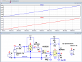
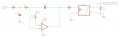
Downloaded the data for the 6051, created a LTS model, ref this plot.
Note: I have split the input and output sections power supplies, that's usually the way for using an opto isolator..
E
EG 1225.png
 

Thread Starter

barg

Joined Dec 23, 2015
129
Even if the motor-side power supply is not particularly stable, why can't is share a 0V connection with the 5V DC? In that case, there wouldn't be a problem to solve.
hi barg,
Downloaded the data for the 6051, created a LTS model, ref this plot.
Note: I have split the input and output sections power supplies, that's usually the way for using an opto isolator..
E
View attachment 257116
Thank you Eric!

That means i need to add a dc source just for the second side opamp.. as if i use the same grounds, it can affect the first side( already test that previously).

Question is, if using the Optofet H11F1- can it be used without adding opamp in the second side just directly to the analog input?
 

LowQCab

Joined Nov 6, 2012
5,102
This Thread could be getting way out in left-field somewhere ..........
There needs to be a concise explanation of the desired end result.
What is the exact problem being solved here ??????, the "30,000-foot view".

And BTW, stop trying to build critical Circuits with
whatever You have in your "Junk-Drawer", and/or, with "Jelly-Bean" parts.
There are excellent reasons why there are
hundreds of thousands of different part numbers to choose from.
.
.
.
 

ericgibbs

Joined Jan 29, 2010
21,585
hi barg,
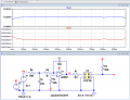
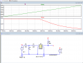
The H11F gives this result with your circuit also tried with a bare-bones sim, the H11 needs about +1V forward bias before it conducts and note the change in polarity,
Also, not linear, as pointed out earlier.

E
EG 1226.pngEG 1227.png
 

Thread Starter

barg

Joined Dec 23, 2015
129
Hi LowQCab,

Yes, i think your answer using optofet was in the right direction. need to pass analog signal from one dc regulated side to unregulated dc second side. in the second side of the H11F1M, it suppose to work without additional opamp ( Preffered to connect directly to the analog input in the motor driver that has an initial 5v with pull up resistor).
 

ericgibbs

Joined Jan 29, 2010
21,585
hi barg,
So there is no misunderstanding, your latest circuit does not work with the H11F1
It needs a minimum forward bias of 1V and the current load at higher voltages is too much for the 6051, also non-linear, it is has the Vout is in the opposite sense
E
 
Top