Are you hoping to repair something? Seeking to purchase items without knowing what they are is a bit unusual.
They do appear to be MOVs, (Metal Oxide Varistors), and those items do often need to be replaced. The repair process is usually a bit more complex than simply replacing a failed component because often some other component has caused the failure. So then the challenge becomes discovering what else may have failed. This forum often is able to provide help in that area if enough information is provided.
Or, if you are experimenting with components, many of us can offer useful information.
Hi, thank for the reply , i'm experimenting to repair code less telephone by my self. i'm interesting on electronic. i found those two components are faulty but i don't know name of them.
model :- uniden Dect 6.0
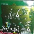
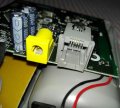
fault :- check TEL line ( please refer the attachment )
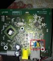
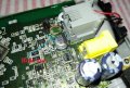
OK, and thanks for the pictures. Now it is clear that the devices are not part of a mains power circuit, but instead they are protecting the phone line input. Does the system function without them? I did see labels next to part outlines and that will provide an indication of what the device is. Usually R= resistor, C= capacitor, D= diode, X=crystal, ZD=zener diode, and Q=transistor, also VAR= varistor (MOV).
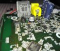
Given that it is a consumer electronic device it is not likely that they are two different types of MOV, so the yellow one is most likely a capacitor, because it appears to have the notation "C51" next to it's outline.
Now I am wondering why you suspect that they need to be replaced. Do you have a meter that you can check them with? If either device shows a low resistance then they would indeed be suspect.
OK, and thanks for the pictures. Now it is clear that the devices are not part of a mains power circuit, but instead they are protecting the phone line input. Does the system function without them? I did see labels next to part outlines and that will provide an indication of what the device is. Usually R= resistor, C= capacitor, D= diode, X=crystal, ZD=zener diode, and Q=transistor, also VAR= varistor (MOV).
Given that it is a consumer electronic device it is not likely that they are two different types of MOV, so the yellow one is most likely a capacitor, because it appears to have the notation "C51" next to it's outline.
Now I am wondering why you suspect that they need to be replaced. Do you have a meter that you can check them with? If either device shows a low resistance then they would indeed be suspect.
Thank for the reply .. system Does not function without them.. but i'm pretty sure system should work without them.. can any one help me to find out it's service manual ? Thank you kind regards.
C is the designation for a capacitor. 120 basically means 12 and "0" zeroes picofarad. It will test open with a multimeter.
The MOV shorts with large surges.
The 12 pf capacitor likely filters RFI. (Radio Frequency Interference)
The number one thing to test is the cable. Telephone cables should be of the crossover type although the Verizon tech that teaches courses had the wrong answer. Examining the plug side to side, the wires on the other plug should be on the opposite side. e.g. pin 3 should go to 4 and vice versa. These are the middle pins of a 6P (6 pole plug). Phone cord is usually 6P, 4C meaning 6 possible poles with 4 populated.
telco:
crossover between telephone set and wall
Straight-thru at patch panels.
Polarity matters on older genuine Bell phones with a keypad. New phones are general agnostic and don't care.
Since you have it apart, check for voltage across the middle pins. Ignoring polarity for now, you should have about 48 Vdc on hook and about 5V on hook. If you don;t have any voltage, check the cord or phone line.
The phone line is usually checked by plugging a known good phone into the NID Network Interface Device) on the outside of the house. One side is for you and the other is for the telco company.
There should be a test jack there which will disconnect all of the internal wiring and connect you to the telephone line when you plug in a phone.
The NID contains a surge suppressor on the telco side. There it's easy to access the line with telco style alligator clips.
The consumer side at a minimum contains a test jack.
This module MAY contain some passive electronics that implement a 1/2 ringer load. With all your phones unplugged, there is still a 1/2 of a standard ringer load on the telephone line.
The DSL splitter may be there too.
If a phone was plugged into the wrong side of a DSL filter, I would think you would get this "check phone line" issue too.
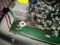
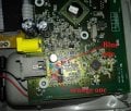
I'd be more concerned with the blown Q4?? and the burnt surface mount resistor?? or whatever.
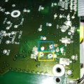
As was mentioned above, are the parts you removed shorted? If no, they are probably ok.
And another thing to note. It looks like you have pulled the feedthoughs out, and top pads off when you removed the Varistors.
If you have to pull hard to get the parts out, the solder is not melted enough. Also, a temperature controlled iron is a good idea. An unregulated iron may get too hot and damage the board.
To remove the transistor, apply a pool of solder across all 3 pins together and carefully remove the transistor when it is freed up
Gently does it.
Then clean up the board with solder wick or a solder sucker.
So now the question is what was it that caused the damage to those damaged parts? To discover that it will be useful to be able to see the circuit, at least the circuit section containing those parts. Is it likely that the damage was caused by lightning nearby? Or a problem with an external power supply? Is a circuit schematic available?
It bothers me that I did not notice that damage initially, it is quite clear in the first photograph.
 Facebook
 Google
 GitHub
 Linkedin
")