 Facebook
 Google
 GitHub
 Linkedin
Hi
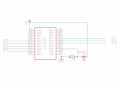
Have this Little project
at AN1 i have a V. controlled by a LDR and a resistor.
When the lights outside be to bright the PIC should do something, and when it's to dark it should do another thing.
Can the analog reading be triggering an interrupt, or do the code has to run over and check the voltage every run. ?
Here is my code. Chip is 16F1509
Code:
#include <htc.h>
#include <stdio.h>
#include <stdlib.h>
#include "lcd.h"
#include <string.h>
__CONFIG (CLKOUTEN_OFF & FCMEN_ON & IESO_OFF & BOREN_OFF & CP_OFF & MCLRE_OFF & PWRTE_ON & WDTE_OFF & FOSC_INTOSC);//XT
__CONFIG (LVP_ON & LPBOR_OFF & BOREN_ON & STVREN_ON & WRT_OFF);
#define _XTAL_FREQ 4000000
#define FOSC 4000000L
volatile signed int light;
volatile bit on;
//global defs

  union
{
unsigned int res;
char bytes[2];
}
ADC;
char ADC_num[6];
float lightintens;

static void interrupt isr(void)   // Here is interrupt function - the name is unimportant.
{
    //no interrupt yet.
}// end interrupt


void setup(void)
{
IRCF3=1;//16MHz clock speed
IRCF2=1;
IRCF1=1;
IRCF0=1;
//REGISTER 5-1: OSCCON: OSCILLATOR CONTROL REGISTER
// bit 6-3 IRCF<3:0>: Internal Oscillator Frequency Select bits
//1111 = 16MHz
//1110 = 8MHz
//1101 = 4MHz
//1100 = 2MHz
//1011 = 1MHz
//1010 = 500 kHz(1)
//1001 = 250 kHz(1)
//1000 = 125 kHz(1)
//0111 = 500 kHz (default upon Reset)
//0110 = 250 kHz
//0101 = 125 kHz
//0100 = 62.5 kHz
//001x = 31.25 kHz
//000x = 31kHz LF
//Port analog / digital
TRISA=0; //all port ud.
TRISA1=1; //set a1 in
TRISB=0; // out
//TRISC=0b11111000;//RC0-RC2 out,RC3-RC7 in,
TRISC=0b00000000;// all other out.
GIE = 0;  // Global interrupt disable just in case
//ANSELA = 0b00000001;  // Set PORT AN0 to analog input AN1 to AN7 digital I/O
ANSELA=0; // set alle digital.
ANSA1=1; //analog
ANSELB=0;
ANSELC=0;//turn off all analog functions


///ADCON0=0b00000000;   // select right justify result. ADC port channel 0

//adcon1
ADFM=1;    //right justified
//ADCS=100; // fosc/4
ADPREF0=1;
ADPREF1=0;
//ADPREF=00; //vref+ = vdd
TRIGSEL0=0;
TRIGSEL1=0;
TRIGSEL2=0;
TRIGSEL3=0;
CHS0=1;  //an1
CHS1=0;
CHS2=0;
CHS3=0;
CHS4=0; // AN1  analog kanal  intern kanal

//timer1 settings
TMR1CS1=1; //CLOCK SOURCE S-ELECTIONS
TMR1CS0=0;
//11 =Timer1 clock source is Capacitive Sensing Oscillator (CAPOSC)
//10 =Timer1 clock source is pin or oscillator:
//If T1OSCEN = 0:
//External clock from T1CKI pin (on the rising edge)
//If T1OSCEN = 1:
//Crystal oscillator on SOSCI/SOSCO pins
//01 =Timer1 clock source is system clock (FOSC)
//00 =Timer1 clock source is instruction clock (FOSC/4)
T1CKPS1=0; // <1:0>: Timer1 Input Clock Prescale Select bits
T1CKPS0=0;
//11 = 1:8 Prescale value
//10 = 1:4 Prescale value
//01 = 1:2 Prescale value
//00 = 1:1 Prescale value
T1OSCEN=1;//LP Oscillator Enable Control bit
//1 = Dedicated Timer1 oscillator circuit enabled
//0 = Dedicated Timer1 oscillator circuit disabled
nT1SYNC=1; //: Timer1 Synchronization Control bit
TMR1ON=0;//: Timer1 On bit
TMR1H = 0x81;     // preset for timer1 MSB register
TMR1L = 0x00;     // preset for timer1 LSB register
TMR1GE=0; // gate for timer1 disable.
//T1GCON: TIMER1 GATE CONTROL REGISTER
//bit 7 TMR1GE: Timer1 Gate Enable bit
//If TMR1ON = 0:
//This bit is ignored
//If TMR1ON = 1:
//1 = Timer1 counting is controlled by the Timer1 gate function
//0 = Timer1 counts regardless of Timer1 gate function
  //Timer1 Interrupt prepare
   TMR1IE=1;// PIE1 register
   PEIE=1; //INTCON register
    //PIR1=0; // Clear all bits PERIPHERAL INTERRUPT REQUEST REGISTER 1

   //todo now in order to generate interrupt GEI=1 and TMR1ON=1

//timer0 settings.
TMR0IE=0; //use timer0 interrupt register.  ÆNDRET
TMR0CS=0; // bruger tæller,
TMR0SE=0; // lav til høj tælning.
IOCIE=0; // enable interrupt on change  ÆNDRET
PSA=1; //not assign prescaler.
//other misc settings
} //end setup


void house_on (void)
{
RC0=1;
__delay_ms(5);
RC0=0;
RC1=1;
__delay_ms(5);
RC1=0;
RC2=1;
__delay_ms(5);
RC2=0;
RC3=1;
__delay_ms(5);
RC3=0;
RC4=1;
__delay_ms(5);
RC4=0;
RC5=1;
__delay_ms(5);
RC5=0;
RC6=1;
__delay_ms(5);
RC6=0;
RC7=1;
__delay_ms(5);
RC7=0;
  }

void lights_on (void)    //to dark or light.
{

                utoa(ADC_num, light, 10);
                if (light>50) on=0;
                if (light<=50)on=1;


}        // END lights on.

void main (void)
{

setup();         //runs setup
        __delay_ms(1000);
  // TMR1ON=1;    // timer1
         on=0;
       GIE=0;        //interrupt off
           while (1)// runs loop

       {
           lights_on();
           if (on==0)
           {

           __delay_ms(1000);
           }
           if (on==1)
           {
               house_on();
           }
         }//end while endless loop
}//End main
Attachments
-
 6.8 KB Views: 28
")


