Amps and Volts in Resistance Heating

ronv

Joined Nov 12, 2008
3,770
Thanks for the feedback, guys. I have redesigned the tip in four different variants. I've attached all four with the hopes that you will all vote on which one you think will perform the best and heat the tip as the application requires. Take a look at my four designs and let me know which one you think will work. I'll be having these made this coming week and will have results the week following.

You'll notice that all of the designs have an extra step much closer to the tip. The video I posted shows how the current flows away from the tip, and I'm hoping less material at the tip (thanks to the step) will make it flow in the opposite direction.

Also notice that the step on 9505-T2A is much closer to the tip than the other three.
#2 I think, but the long slot on both sides.
 

ronv

Joined Nov 12, 2008
3,770
Thanks for the feedback, ronv. What are your thoughts on the location of the last step? There are two versions of the tip that have a straight slot. Each has a different step location.
I think (only think, don't know) the horizontal slot helps to isolate the tip (in terms of heat) from the body. So it concentrates the heat in the tip as opposed to up and down the tube.
 

Thread Starter

amspurge

Joined Jan 15, 2016
50
I think (only think, don't know) the horizontal slot helps to isolate the tip (in terms of heat) from the body. So it concentrates the heat in the tip as opposed to up and down the tube.
Possibly, the only thing that makes me think differently is that there is a cooling tube that goes down the center of the tip to rapidly cool the tip. Successful tips are able to cool back down to about 100 degrees in a couple seconds with a nice air blast. Just makes me question if the slots are for isolating the heat. I've always wondered if they are for equal air flow over the tip.
 

#12

Joined Nov 30, 2010
18,224
I'm with ronv on this one. A "T" slot on each side will force the current into the tip region and protect the heat from escaping into the main tube (partially). And that's the best you can hope for. After all, you have to leave some metal to support the tip mechanically unless you make a ceramic collar. That would be rather exotic for the budget.;)
 

strantor

Joined Oct 3, 2010
6,875
I vote for "2A." I feel uneasy contradicting @#12 after he's just recently been named the forum's thermodynamics expert, but what the hell, the points don't matter, right?

I vote for design "2A" because as we've seen, the "T-slot" focuses the heat at the two opposite sides of the tip instead of evenly around it. I think it would be best to abandon the T-slot. So for me it's between 2A and 1A. I picked 2A over 1A because the "step" is just at the very tip. I think this will help focus the heat at the tip instead of along an appreciable length of the barrel. It will also be less metal to cool off afterward and should cool off much faster (as well as heat up much faster).
 

WBahn

Joined Mar 31, 2012
33,069
I would say that a modest T slot (if it's too aggressive then the metal bridge adjacent to the tip face becomes the primary heating element) is what you want.

I think the biggest factor would be to get the slot cut as far down to the tip as possible. Imagine taking a disk, which is the actual tip face, and connecting leads on both sides. If you just barely touch the leads to opposite edges of the disk you get the most resistance between the contacts and, hence the most heat. But that is then concentrating all the current at two small points which does two bad things -- it causes the disk to heat up at those points much faster than the in the center, and it causes the lead to heat up too much. So you spread the lead contacts out partly around the perimeter of the disk. Do this too much and you greatly reduce the effective resistance of the disk as seen between the contacts. If the slot doesn't extend down to the tip face, then you effectively have a collar around the tip which reduces the current going through the face. If the collar is too tall then nearly all of the current will go through it and little will go through the face. It will also increase the thermal time constant both for heating and cooling. Of course, if it's missing or too short, then you may lack mechanical strength in the tip face.
 

Thread Starter

amspurge

Joined Jan 15, 2016
50
Thanks for all the responses, fellas. I gain a little more knowledge with each post.

I will be making two of each tip that I designed and will be testing in about a week (have to send them out for wire EDM). I will report my findings.

Once the tip design is proven, I'll need to move on to the transformer portion of the design. Does anyone have any suggestions on how to go about doing this? What can I do to reverse engineer the proven transformer that I have sitting in my lab?
 

Thread Starter

amspurge

Joined Jan 15, 2016
50
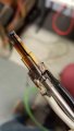
Thanks for the input, tkng211. I will make a design like this and make two of them this week. There are tips with similar cuts on the market. I was testing one this week with a similar concept (see attached). You can see that the tip is not square and actually is cut at an angle. The slot appears to account for this geometry.
 

Attachments

Thread Starter

amspurge

Joined Jan 15, 2016
50
Ok guys, I want to make a tip with a radical design that is much different from the ones that I posted. I searched Google for "resistance heating" for inspiration, but I have yet to be inspired.

If you guys have any radical designs (or practical), let me know!
 

Thread Starter

amspurge

Joined Jan 15, 2016
50
I'm with ronv on this one. A "T" slot on each side will force the current into the tip region and protect the heat from escaping into the main tube (partially). And that's the best you can hope for. After all, you have to leave some metal to support the tip mechanically unless you make a ceramic collar. That would be rather exotic for the budget.;)
If you watch the video, you'll see that the first heat cycle starts at the "T" and goes up the tip rather than to the end. Then the second heat cycle starts at the "T" and goes in both directions. Do you think the current moved more towards the end because of an increase in resistance of the upper portion from the first heat cycle?
 

#12

Joined Nov 30, 2010
18,224
Do you think the current moved more towards the end because of an increase in resistance of the upper portion from the first heat cycle?
One of the characteristics of copper is that it has more resistance when hot, so that might be what's going on. The second burst of energy finds the cool parts more conductive, so it goes there more than it did the first time.
 

strantor

Joined Oct 3, 2010
6,875
Ok guys, I want to make a tip with a radical design that is much different from the ones that I posted. I searched Google for "resistance heating" for inspiration, but I have yet to be inspired.

If you guys have any radical designs (or practical), let me know!
I guess the design I described in post #17 isn't radical enough? Or maybe I just didn't describe it in ways that survive first contact with the atmosphere outside my brain. If I have time later tonight I'll draw it in SketchUp.

I see a few advantages to the design I described;
#1 it should work like you want.
#2 while it sounds more complicated than the designs you're currently considering (and technically may be, considering there's two parts), it may actually be cheaper to manufacture considering the entire assembly is machined only on a lathe. Most machining costs come from setup. If you have to set up multiple machines for a production run, it costs more. It takes 2 machines to make what you're using now; a lathe and a mill (or maybe that slot is cut by plasma or laser or EDM or waterjet, or some other fancy contraption I don't know about ).
#3 it will probably cool faster because the air jet will not escape out the sides of a slit. It will be contained within the tip and be guided the entire way to the tip, and exit through vent holes at the tip.
 

Thread Starter

amspurge

Joined Jan 15, 2016
50
I guess the design I described in post #17 isn't radical enough? Or maybe I just didn't describe it in ways that survive first contact with the atmosphere outside my brain. If I have time later tonight I'll draw it in SketchUp.
Hey strantor,

I thought the idea, at the time, would be too difficult to machine, but after a second read, I think it may be possible. I would have to braze the two parts together and find a way to get air to the tip for cooling (also need slots for air escapement).

I'm going to draw up a design and have it made!
 

strantor

Joined Oct 3, 2010
6,875
Hey strantor,

I thought the idea, at the time, would be too difficult to machine, but after a second read, I think it may be possible. I would have to braze the two parts together and find a way to get air to the tip for cooling (also need slots for air escapement).

I'm going to draw up a design and have it made!

here's a visual. Not exactly as I wanted to draw it but I'm out of time...
element1.png element2.png element3.png element4.png element5.png
 

Thread Starter

amspurge

Joined Jan 15, 2016
50
here's a visual. Not exactly as I wanted to draw it but I'm out of time...
I think the concept is good, but after trying a design, I'm not sure how to get the cooling to the tip. See attached design. I designed it with 16ga wires.
Just need to find a way to get cooling down the tip.
 

Attachments

strantor

Joined Oct 3, 2010
6,875
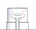
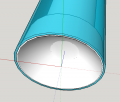
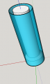
how badly do you need the arched cup in the center? what if that were gone? (like a straight tube hot at the end, hollow in the middle)
 

ronv

Joined Nov 12, 2008
3,770
Thanks for the input, tkng211. I will make a design like this and make two of them this week. There are tips with similar cuts on the market. I was testing one this week with a similar concept (see attached). You can see that the tip is not square and actually is cut at an angle. The slot appears to account for this geometry.
In the picture it looks like the tip is thinner than the barrel. Is that true?


Thread Starter

amspurge

Joined Jan 15, 2016
50
In the picture it looks like the tip is thinner than the barrel. Is that true?
Yes, the tip has a step and is thinner. The video shows an ineffective tip that does not have the step, so all the tips I will be making this week have the step.
 
Top