Thanks to all of the people those who came to help me I am really grateful to all of you specially papabravo he showed me the right way to do it but now I am facing a new problem but I am trying to solve it, in case I could not solve the problem I will start a new thread thanks to all
"I suppose it is tempting, if the only tool you have is a hammer, to treat everything as if it were a nail."
- Abraham Maslow, Professor of Psychology at Brandeis University, "The Psychology of Science: A Reconnaissance", 1966
"I suppose it is tempting, if the only tool you have is a hammer, to treat everything as if it were a nail."
- Abraham Maslow, Professor of Psychology at Brandeis University, "The Psychology of Science: A Reconnaissance", 1966
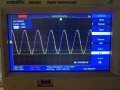
I am trying to amplify the current of a 4Vpp 90KHz sine wave produced from an oscillator to get about 50mA of current yesterday I posted a thread about that in analog and mixed signal design, I got some help and finally I have been able to draw my desired current(50mA) from the emitter follower config but somehow due to some unknown reason to me,the some portion of the negative part of the sine wave is getting clipped,I am uploading the input and output waveforms as well as my ckt diagrams,please someone help.
Yellow trace is the input and violet is the output
note: Currently I am in 4th sem of my B.Tech(ECE) and all they taught us in class is that keep the q point at the middle of the load line to get a stable biasing as well as the full 360 degree swing
The scope trace looks normal to me. Clipping would look like a flat segment at the bottom of the negative peak. You don't have to use precisely Vcc/2 for the Q-point. You can adjust it up or down slightly to provide additional margin for either the positive or negative peaks.
The scope trace looks normal to me. Clipping would look like a flat segment at the bottom of the negative peak. You don't have to use precisely Vcc/2 for the Q-point. You can adjust it up or down slightly to provide additional margin for either the positive or negative peaks.
please look carefully at the violet trace you will notice the clipping and I have already tried sliding q point up and down but no matter what I do some portion of the negative part is always getting clipped
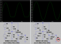
I am attaching another picture it is of yesterday's result here the amplitude is set to 5.24V,today I lowered that to 4V but then also it is happening
note: yesterday yellow trace was output but today violet trace is the otput
Yes, well forgive me, but the scope traces in post#28 and post #30 are different and the violet trace was obscured by the cursor. So you either need to reduce the input signal or raise the supply voltage to handle the larger input signal.
Yes, well forgive me, but the scope traces in post#28 and post #30 are different and the violet trace was obscured by the cursor. So you either need to reduce the input signal or raise the supply voltage to handle the larger input signal.
Again sir, I already have tried raising the dc supply to 20V, it does nothing,I have tried changing the emitter resistor for different bias voltage also and really it isn't making any difference, actually no matter how or what I do,it isn't making any difference, that's why I changed the transistor from 2n3904 to CL100S but then also nothing! .I kept scratching my head through out the whole day thinking about what is going wrong but could not find any solution that's why I am posting this here to get some expert help like yesterday
Again sir, I already have tried raising the dc supply to 20V, it does nothing,I have tried changing the emitter resistor for different bias voltage also and really it isn't making any difference, actually no matter how or what I do,it isn't making any difference, that's why I changed the transistor from 2n3904 to CL100S but then also nothing! .I kept scratching my head through out the whole day thinking about what is going wrong but could not find any solution that's why I am posting this here to get some expert help like yesterday
Of course the negative output is clipping.
The transistor pulls the output properly towards the positive supply but the emitter resistor drives the output negatively but forms a voltage divider reducing the negative output voltage.
You need a reduced value for R1, R2 and R3 (and fry the transistor), a higher value for R4 or a push-pull pair of transistors.
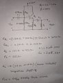
This is the whole schematics
edit:Op amp used TL-084 and transistor used 2n6292 you need not to worry about the power supply it can provide upto 24V 2A