I'm just a dilettante. My simulation doesn't even have a real microphone model in it, just an AC source of a few mV.
A super pre-amp would be nice, but if it turns out just a good pre-amp that's good enough. Might learn a few things along the way.
Trying my hand at math now, to see what noise carbon/film resistors might introduce.
Yep, an OPA134 would be an excellent choice. I actually have quite a few of those kicking around here. Metal film resistors will be more quiet than carbon film.
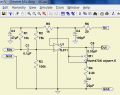
So I've built this circuit, running on a 9v battery. Amplification 225x. Plugged into a sound card line in and made a few recordings. Recording music that is about 85db at the mic sounds good.
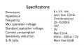
I'd like to record some nature sounds that are much much quieter than 85db, and there is obviously a noise floor with these tiny electret mics. Looking at the specs from these mics how do I figure out the noise floor?
If I wanted to go shopping for an electret with a low noise floor, is there a way to tell how each one compares to others when it comes to the noise floor?
I just measured the output from my amp circuit -22db in a quiet room. And -55db with the electret capsule shorted. So the pre-amp is pretty quiet.
There it is (I think) Measured at 1 Pa or 92 db minus 65 db s/n leaves 27 db. About like the sound in a bedroom at night.
I'm not sure you will find much better because most of the noise is the little amplifier inside the microphone. You might be able to swap it out with a better one I suppose.
This might be useful. http://www.analog.com/library/analo...-05/understanding_microphone_sensitivity.html
I custom built a stereo microphone from arrays of 5 mic capsules in parallel at each channel. Such an array assembly helps to dramatically raise the S/N ratio: the audio signals from the capsules add up because of their synchronicity while the noise from the individual capsules (which is stochastic) tends to cancel out. The mics I used had a sensitivity of -58dB (IIRC), the best I could get at this size and at a reasonable cost at that time. I estimated that the sensitivity of the whole assembly (microphone array and dish) is comparable to that of a human ear. Not bad!
It probably isn't even close to being like a human ear, which can adjust down to 0 db I think. But does this practice of paralleling mics work in theory and practice?
#12, so you like my idea of turning R4 into a pot and VR1 into a fixed resistor? What about my theory about noise at very high gain? Would a 1K pot be realistically quieter at the R4 position, than a 500K pot at VR1?
Do you really need a gain of 228?
Even if you do, I would see about reducing the impedance of that feedback loop.
If you're looking at an input voltage peak of 17.5 millivolts peak to hit the 9 volt rail, that is all the voltage that will be applied to the grounding resistor in the feedback loop. The TL-071 can easily drive 1 ma, so that suggests a resistor of 18 ohms to ground and a feedback resistor of 4k. See where I'm going here?
The cost will be in the size of C2. If it has to pass 40 Hz at 18 ohms (math math math) that's 220 uf. Not so bad in a world where you can get 220 uf for 15 cents.
These ideas suggest that some very reasonable values can be had here, like a 100 ohms to ground in series with a 1k pot and a 22k feedback resistor.
I've had this working for a while but I am trying to rebuild it better and stronger and also trying to understand it better in the process.
I've looked at a few spec sheets for electret microphones, and most of them say operating voltage 1.5V to 3V, with a max voltage sometimes in the 5V range, sometimes higher into the 9V range.
Doesn't the circuit in post #1 pull up the mic to 9V? Is it not better to operate near operating range for the mic and not absolute max?
If there were 9V across R1 (which it isn't) the maximum current through R1 would be 9V / 10 kΩ = 0.9mA.
We don't know how much current the electret microphone is conducting. If it were 0.5 mA, then the voltage across R1 would be 5V. The voltage at the microphone would be lower than 4V.
R1 limits the current and voltage seen by the electret microphone.
Note that the JFET in the microphone has to be biased in the linear region. Hence 4V bias would be about right.
We don't know how much current the electret microphone is conducting. If it were 0.5 mA, then the voltage across R1 would be 5V. The voltage at the microphone would be lower than 4V.
That's the part I was curious about. If R1 value was just a genetic recommendation. I want to use an array of microphones to decrease noise. Maybe 10 or more. So I imagine that the R1 value would need to be adjusted in such a scenario.
Here is the spec sheet for one of the more popular electrets on Digikey, if quantity in stock is a proxy for popularity.
Is there any theoretical difference in how this microphone, or others of similar design, will behave if it's operated at 1.5V vs. 10V?
I think I understand now the way to set the resistor value properly. If I have an array of microphones, I'd just need to measure their total current and using that set the resistor to the voltage I want to run them at.
But does voltage affect the way the FET inside the mic acts? I was watching a Youtube video and it was touched upon briefly how FET voltage affects gain? Are there any other side effects of running at over 1.5V? It says up to 10V, so that's the part where my knowledge is lacking.
When they state MAX OPERATING VOLTAGE, they are stating safe operating voltage before the device could be permanently damaged, allowing for a given amount of safety margin.
If they state STANDARD OPERATING VOLTAGE, that is where you want to be. If you want to keep the noise low, you want to operate at a lower current and lower temperature. For low noise levels, we cool our semiconductor devices with liquid nitrogen which has a boiling point of slightly above -200 °C. But that is a different story altogether.
Think of the JFET inside the Microphone as being an unknown Resistor.
Then the Mic-Amp, and Resistor #R1, become a basic "Voltage-Divider-Circuit".
The ideal Voltage created by the Voltage-Divider should be
close to 1/2 of the maximum rated Voltage of the Mic.
This will provide the maximum Output-Voltage before Amp-Clipping starts to kick-in.
This means that the Mic will not be prematurely overloaded by high SPL sounds.
Every Electret-Mic has a maximum SPL rating that it can handle without going into Clipping,
but this information is usually not provided by the manufacturer.
There are external modifications that can be made to many Electret-Mics that
will enable higher SPL levels to be handled without increased distortion.
The Outputs and Grounds for multiple Electret-Mics can all be connected in parallel,
but the Bias-Resistors, ( 1 for each Mic ), should be rated at 1%, or better, tolerance relative to each other.
Use the Schematic provided by MrChips above, but set the Bias-Voltage to half by changing #R2.
R2 can be temporarily replaced by a Pot to find the ideal Bias-Voltage,
then the Pot should be replaced with an appropriately sized Resistor.
Also add a 100nF Ceramic-Capacitor in parallel with the 47uF Electrolytic-Capacitor.
Keep in mind that using multiple Mics WILL result in a "combing-effect"
on the collective-Frequency-Response of the group of Microphones. This will vary, depending upon the physical mounting distance between the Microphones,
but it will usually be confined to Frequencies somewhere above ~8KHz or so.
.
.
.
 Facebook
 Google
 GitHub
 Linkedin