Amplifying a 2.5V Square wave coming from a microcontroller?

Thread Starter

sarahtelayrii

Joined May 2, 2009
12
Hi,

I'm just asking for some assistance since I'm not sure of amplifiers much.

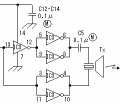
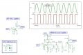
My question is that I've programmed my PIC micro that is emitting a Square wave 2.5V peak to peak to a transducer that can handle up to 140V, the thing is that I need to amplify this signal to at least 10 times so it's 25V peak to peak if possible at the output?? A overall gain of 10 times or higher.

I'm stuck between choosing between a opamp? voltage comparator? to amplify the voltage? I'm good in programming micros and electric circuits but when it comes to electronics part ive been somewhat confused in the amplifiers area. Also I checked my uni books however it explains only theory and there's no mention of any practical application (there's only info on sine waves, not square waves) that meets my need.

I have a 9V rail as well if need be. So any push in the right direction would be loved! thanks...
 
Last edited:

bertus

Joined Apr 5, 2008
22,276
Hello,

Can the transducer also a squarewave signal?
What power is expected at the transducer?
What is the impedance of the transducer?
What will be the frequency range?

Greetings,
Bertus
 

Thread Starter

sarahtelayrii

Joined May 2, 2009
12
* Yes the transducer can take in square waves
* yes the transducer can operate > 20KHz. I'll be using it at around 38KHz

I'm not worried about the impedance of the transducer, I just would like to know what type of circuit I could use to get that 10 gain output (25v output from a 2.5v square wave signal input coming from the micro)??

thanks

edit: its ultrasonic transducer btw
 

Thread Starter

sarahtelayrii

Joined May 2, 2009
12
Ahh sorry btw in my debugging I found that the ultrasonic transducer can handle greater than 150KHz...

the whole project runs of a 9V battery.
 

Thread Starter

sarahtelayrii

Joined May 2, 2009
12
ahhh..heh. thanks but that looks pretty complex for comfort and i dont think it would fit on a breadboard...ive seen projects where they use simple voltage comparators or opamps..something like that should be fine.
 

CDRIVE

Joined Jul 1, 2008
2,219
I'm assuming that this is a maritime transducer. Either way you have to be concerned about its impedance because that's the only way your going to get an intelligent answer to your question, as these are power devices. This dictates that the design of the amp be a power amplifier. Do you understand the difference between a voltage & a power amplifier? Also,.. is your pic going to output a burst?
 

Thread Starter

sarahtelayrii

Joined May 2, 2009
12
its actually a normal ultrasonic transducer...here's the data sheet:
http://www.jaycar.com.au/products_uploaded/AU5550.pdf

I just want a detection range of about 2-3 meters....mine so far can detect about 20cm without any amplification...

The PIC is sending out a continuous square wave 5V p-p, not as a burst.

Also at my uni Im not majoring in electronics so electronics is not compulsory subject for me to do, however I did take an electronics elective but they didnt talk about a power amplifier...

BTW the pulse is now on 40KHz and its still the same, around 20cm. I tested this by placing flat book high enough to see a response on the oscilloscope, the response is at around 20cm, anything further than this the receiver doesn't pick up implying that the range of the transmitter is only about 20cm.

The sensitivity for both the transducers for transmit/receive is around close to 40KHz.
 
Last edited:

eblc1388

Joined Nov 28, 2008
1,542
A few suggestions:

1. Your model of ultrasonic transducer is very frequency selective and should be driven with a signal as close to 40KHz(the spec) as possible to get the highest output. Alternatively, you can monitor the receiver signal and adjust the 40KHz frequency up/down a bit to get the maximum response.

2. Using a signal generator, you can feed a 40KHz voltage adjustable up to 20V pk-pk into the transducer. You can then monitor the receiver response to find out if higher voltage drive really give you the increased distance, before you actually build the amplifier.

3. Output stage suggested by bertus above is the best for your 9V battery as it puts out about ~17V or more pk-pk to the transducer. However, you'll need to add an additional simple interface between the 0-5V PIC output and that amplifier stage.
 

bertus

Joined Apr 5, 2008
22,276
Hello,

Did you put an 5 Vtt (2.5 Vdc) squarewave at the input?
The two outputs are out of phase, this will double the output voltage.
The 7406 is for 5 Volts only.
The 4069 as used in the schematic I gave you can be used upto 12 Volts.

Greetings,
Bertus
 

eblc1388

Joined Nov 28, 2008
1,542
sarahtelayrii, please note comments by bertus.

Here is one done in LTSpice, the "free to use" Spice simulator.

Note: The CD40106B is supplied by 9V in order to generate a 18V Pk-Pk output. As such a NPN transistor is required to interface with the PIC output which is 0~5V.


Attachments

Last edited:

CDRIVE

Joined Jul 1, 2008
2,219
I must admit that is a brief data sheet and it doesn't mention impedance at all. Now I understand why you weren't concerned about it. It looks like power transfer is not an issue here.

Here's a schematic that includes a simple single stage BJT (Q3) that will deliver 60V square waves to a high Z transducer. Since the transducer is resonant it will filter the square wave (some what) when connected to it.

In the event that your transducer doesn't like square waves, I've included a resonant 40KHz JFET amplifier. The outputs from the two amps can be seen in the graph. You can see clearly how the 5V square wave input is converted to a sine wave (top plot) on the output of the resonant amp.

The circuit in the box is just the test source to simulate the ouput of your Pic.
 

Attachments

CDRIVE

Joined Jul 1, 2008
2,219
sarahtelayrii, please note comments by bertus.

Here is one done in LTSpice, the "free to use" Spice simulator.

Note: The CD40106B is supplied by 9V in order to generate a 18V Pk-Pk output. As such a NPN transistor is required to interface with the PIC output which is 0~5V.
Curious why you modeled the xdcr as a cap? :confused:
 

eblc1388

Joined Nov 28, 2008
1,542
Curious why you modeled the xdcr as a cap? :confused:
It was meant for a load to show the voltage produces by the output stages only. I haven't gone into the trouble to look up the exact model of an ultrasonic transducer but I assume it should be a capacitor in parallel with a resistor.

Do you have any suggestion on how best to model it instead? Please share with us.

I don't know why you have come up with a circuit using 60V? See the original post by the OP.

sarahtelayrii said:
the whole project runs off a 9V battery.
 

Thread Starter

sarahtelayrii

Joined May 2, 2009
12
Hi,

I talked with a technician I know at my university today, and he suggested a way to drive 9V up to 18V, with the input being a 0 to +5V square wave.

It's basically like this:
http://instruct1.cit.cornell.edu/co...49_mar97/jjl49_mar97/index_files/image006.jpg

However instead of just being the one LM311, there is a 2nd LM311 just below it but that is inverted with - top and + being on bottom. This too connected to 9V and with a 330ohm resistor. I've got the parts and Ill try it out now. I'll post the complete schematic later on.

However if I measure the output pin of the square wave signal coming from the micro, for the value of the voltage it's at 2.5V, though there's a square wave on the oscilloscope going from -2.5 to 2.5V from a 5V regulator source and not from 0V to +5V square wave. I asked him about this and he said most likely the oscilloscope was on ac coupling and not dc hence it not being 0 to +5, but I'll see what the result would be once everything connected via a multimeter.

Also just wanna say thanks again I really appreciate it, it just shows that I'll need to go over my electronics book one more time from way back last year in my spare time after all this is done.
 
Last edited:

CDRIVE

Joined Jul 1, 2008
2,219
It was meant for a load to show the voltage produces by the output stages only. I haven't gone into the trouble to look up the exact model of an ultrasonic transducer but I assume it should be a capacitor in parallel with a resistor.

Do you have any suggestion on how best to model it instead? Please share with us.

I don't know why you have come up with a circuit using 60V? See the original post by the OP.
I chose 60V because the XDCR data sheet (that the OP posted) states that the max input voltage = 140VPP. So 60V is well within its max spec. The OP's first post stated that he wanted a voltage gain of at least 10. This would be 50VPP since the PIC output= 5VPP.

Please note that the data sheet does not spec the drive signal as steady state. I asked the OP if the PIC was going to burst tone the xdcr and he replied no. Even at half the max 140VPP (which my circuits are) I would not expect that a continuous signal to be healthy for the transducer.

Lastly, since the data sheet makes no reference to input impedance of the xdcr I treated it as a very Hi Q parallel resonant load. ;)
 
Top