Amplifier output getting saturated/distorted

Thread Starter

Dritech

Joined Sep 21, 2011
901
Hi all,

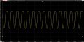
I am using the amplifier circuit below and for some reason, the output is getting saturated then the gain is approx 50% (please see 1st attachment)
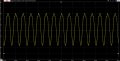
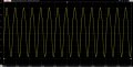
If I continue increasing the gain, the output will eventually start taking shape, but still being distorted.

Any clue of what may be causing this please?

1596354041186.png
 

Attachments

Thread Starter

Dritech

Joined Sep 21, 2011
901
Hi ericgibbs,

the supply voltage is 5V, driving source is a LPF (schematic below), and the output load is a 100k resistor.

1596355681192.png
 

Thread Starter

Dritech

Joined Sep 21, 2011
901
hi D,
Please check my LTS circuit for correctness.
This shows a poor AC analysis sweep.?
E
So the circuit is not well designed? I don't recall having any problems when I built this circuit on a breaboard. The only dirrenence is that the amplifier feedback pat was 100K and the input resistor was 7.15K. Could this change contribute to this distortion?
 

Thread Starter

Dritech

Joined Sep 21, 2011
901
@ericgibbs Thanks a lot for your support.
Something which I forgot to mention is that before the LPF, there is a HFP stage (shown below)

i.e. Input signal --> HPF --> LPF --> Amplifier

I just replaced the pot and resistor of the amplifier, but nothing changed.

Below are the specs:
* HPF (-3dB at 6Hz)
* LPF (-3dB at 600Hz)
* Amp (gain 1 up to 15)
* Power supply (single supply 5V, but I intend to also use it at 3.3V)

My problem is that I already designed and manufactured the PCB (for the 3rd time :/ ) for this signal conditioning circuit, so hopefully I will manage to solve this problem by just changing the values.

1596361739913.png
 

Thread Starter

Dritech

Joined Sep 21, 2011
901
@ericgibbs , below is the frequency responce for the circuit. For me it looks fine (unless I'm missing something). So what are you suggesting please?

EDIT: Tried at different frequencies (15Hz, 30Hz, 100Hz, 300Hz), but getting the same saturation/distortion at every frequency.

1596363781141.png
 
Last edited:

ericgibbs

Joined Jan 29, 2010
18,766
hi,
The frequency response in LTS looks close to the one you posted.
The addition of the HP section was important.
Do you have the spec of the input signal,. ie: amplitude and frequency range etc..?
I will run further tests using that signal spec.
E
 

ericgibbs

Joined Jan 29, 2010
18,766
hi,
I have tries various sine wave inputs from 10mVpk to 160mV [ at which the Vout clips at ~2.5Vpk] at a centre frequency of 300Hz,
Varied the Gain from ~1 thru 14, no problems.
I cannot see the distortion you have reported.?

E
 

Attachments

ericgibbs

Joined Jan 29, 2010
18,766
hi,
Do you have a complete circuit you could post and if its a PCB layout, a photo of both sides of the PCB would help.
Show the power supply circuit detail.
E

NOTE: I see that your plots Post #1 are centred about 2V Out, yet your Vs = 5V and Vs/2 should equal 2.5v.??


Update:
This is the circuit with Vs=3.3v [ Vs/2=1.65], looks OK.
 

Attachments

Last edited:

Thread Starter

Dritech

Joined Sep 21, 2011
901
hi,
The frequency response in LTS looks close to the one you posted.
The addition of the HP section was important.
Do you have the spec of the input signal,. ie: amplitude and frequency range etc..?
I will run further tests using that signal spec.
E
the input signal has a frequency range of around 8-30Hz and amplitude of around 1Vp-p.
 

ericgibbs

Joined Jan 29, 2010
18,766
hi,
This is with 20Hz at 1Vppk Sine Input
The maximum permitted gain will around times 3.5, then the Vout will clip.

Why is your plot showing a centre Vout of 2V .??

E
 

Attachments

Audioguru again

Joined Oct 21, 2019
6,673
A simulation program does not know about input offset voltage, or about maximum output current.

or

I betcha that the defective opamps were bought on ebay.
 
Top