Amplifier of a voltage gain on 1000 using 2 NPN

WBahn

Joined Mar 31, 2012
33,309
MOD NOTE: Moved to Homework Help.

I moved this to Homework Help because it's pretty apparent that the purpose of you being given this task is not to end up with an amplifier that has a gain of 1000, but for you to learn something about designing multi-stage amplifiers. That goal is best served if you are guided, however painfully for everyone involved, from wherever your current understandings (and misunderstandings) are toward a solution.
 

WBahn

Joined Mar 31, 2012
33,309
Your signal source says it is 1 µA, even though it is called Ve, which implies it's a voltage.

Is that a typo?

If so, what is the scale of your input signal?

Where is your output voltage being taken? I'm guessing it's at the collector of Q2, but engineering is not about guessing -- make your intentions explicit.
 

Thread Starter

Philou42

Joined Oct 30, 2023
24
Your signal source says it is 1 µA, even though it is called Ve, which implies it's a voltage.

Is that a typo?

If so, what is the scale of your input signal?

Where is your output voltage being taken? I'm guessing it's at the collector of Q2, but engineering is not about guessing -- make your intentions explicit.
Yes, Ve could be expressed as Vin, and Vout is taken out of CQ2. Ve is 2uA pic to pic. On the simulations, i effectively have a gain of 1000 ( 2mA on the CQ2 ) the fact is i can't find the mathematic epxression of Vs ( Vout ) / Ve ( Vin )
 

WBahn

Joined Mar 31, 2012
33,309
Yes, Ve could be expressed as Vin, and Vout is taken out of CQ2. Ve is 2uA pic to pic. On the simulations, i effectively have a gain of 1000 ( 2mA on the CQ2 ) the fact is i can't find the mathematic epxression of Vs ( Vout ) / Ve ( Vin )
You are looking for a voltage gain, but 2 mA is NOT a voltage, it is a current.

Is your input signal a voltage, or is it a current?

Is your output signal a voltage, or is it a current?

If either is a current, you are not looking for a voltage gain. If one is a current and the other is a voltage, then you have either a transimpedance or a transconductance amplifier. If the output is a current, then you need to indicate how that current is being taken out of the amplifier -- it can't be open circuit. Each of these types of amplifiers is a very different critter.
 

Thread Starter

Philou42

Joined Oct 30, 2023
24
You are looking for a voltage gain, but 2 mA is NOT a voltage, it is a current.

Is your input signal a voltage, or is it a current?

Is your output signal a voltage, or is it a current?

If either is a current, you are not looking for a voltage gain. If one is a current and the other is a voltage, then you have either a transimpedance or a transconductance amplifier. If the output is a current, then you need to indicate how that current is being taken out of the amplifier -- it can't be open circuit. Each of these types of amplifiers is a very different critter.
OMG i'm so ******, ofc it's a voltage, it's 2uV ! My bad... This circuit as been tested as a Voltage Amplifier of 1000, that's a fact. Now, i need to express by calculations the Voltage gain of this circuits, or either, find a more effecient way to do it. That's why i'm asking for help ( My bad for this mistake )
 

WBahn

Joined Mar 31, 2012
33,309
Without it, i can't have Ic2 = beta*Ib2, i cheked it with simulations (maybe you have a better option, i'm here for that ! ). Either, it does affect the gain.
How does having it allow you to use that equation?

Oh, it will affect the gain, but only indirectly. The first stage has a certain output impedance and RB22 acts as a load on it that is in parallel with the load presented by Q2. If the output impedance of the first stage is low enough, then RB22 has almost no effect on how much current is drawn by Q2.

You don't want to design circuits based on the beta of a transistor -- this is a very poorly characterized parameter of a transistor that varies significantly from one transistor to another, even from the same batch, and also varies enormously over different operating points of the same transistor, not to mention over temperature. If your design relies on a particular transistor beta to work. then it is a poor design.
 

Thread Starter

Philou42

Joined Oct 30, 2023
24
How does having it allow you to use that equation?

Oh, it will affect the gain, but only indirectly. The first stage has a certain output impedance and RB22 acts as a load on it that is in parallel with the load presented by Q2. If the output impedance of the first stage is low enough, then RB22 has almost no effect on how much current is drawn by Q2.

You don't want to design circuits based on the beta of a transistor -- this is a very poorly characterized parameter of a transistor that varies significantly from one transistor to another, even from the same batch, and also varies enormously over different operating points of the same transistor, not to mention over temperature. If your design relies on a particular transistor beta to work. then it is a poor design.
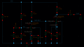
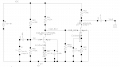
Here, the exercice is to do a circuit, with 2 NPN 2N2222, and they should not be seperated by a condensator, with a voltage gain of 60dB at 1khz. Both should be in Linear mode, so it involve that Ic1 = beta*Ib1 and Ic2 = beta*Ib2 AND Vce1 > Vcesat , Vce2 > Vcesat . This circuit does work with severals references of NPN. I tested it, also on severals simulators. The fact is i can't find the mathematic expression of this voltage gain. I'm asking for that. Or either, another design. Here is an exemple :
1698680462759.png1698680462759.png
 
Last edited by a moderator:

WBahn

Joined Mar 31, 2012
33,309
Have you analyzed the DC operating point of that circuit yet?

That's the first step.

Make sure that the transistors are biased in the linear region before going on.

Then, have you determined the transconductance of the transistors at their operating point?
 

Thread Starter

Philou42

Joined Oct 30, 2023
24
Have you analyzed the DC operating point of that circuit yet?

That's the first step.

Make sure that the transistors are biased in the linear region before going on.

Then, have you determined the transconductance of the transistors at their operating point?
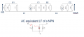
Already done that, DC analysis goes pretty well, AC analysis is like... Something else, that's here where i'm maybe not good enough in maths. Here's what i did1698682232290.png
 

crutschow

Joined Mar 14, 2008
38,909
The voltage to current gain (transconductance) of a BJT is Ic / Vt where Vt is the thermal voltage (≈26mV @ room temp).
That's the formula to use to calculate the gain.
 

BobTPH

Joined Jun 5, 2013
11,665
The correct way to control the gain is to split the emitter resistor into two in series and bypass only one of them with the capacitor. Then the gain is approximately the ratio of the collector resistor to the non-bypassed emitter resistor.
 

Thread Starter

Philou42

Joined Oct 30, 2023
24
There won't be a simple expression, because the impedances of the components around one transistor affect the performance of the other transistor.
Totally, this is why the design of this design is hard, and that's why i'm asking for help.
 
Top