Facebook
 Google
 GitHub
 Linkedin


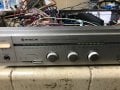
Hitachi experimented with some sort of "Super Linear Circuit" in the late 70s/early 80s. It only appeared in two models as far as I know, the HA3700 and HA4700.
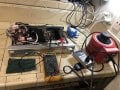
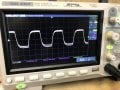
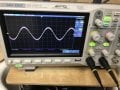
I've been servicing a HA4700, a 50w/ch int amp, for a while and it (finally!!) seems to be working okay now (biasing, set holding bias, low DC offset, producing clean sine and square waves, etc).
Along with a bunch of other components and upgrades, I did replace all both pairs of output transistors from orig Fujitsu 2sc2525 / 2sa1075 to Sanken 2sc1922/2sa1216 .
Idle power consumption is a very normal 28W at the 120 mains; and the pwr. transistors run cool idling at bias of 7.7mV per serv manual ....
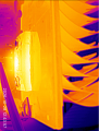
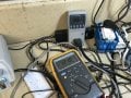
But ... man, I'm afraid to push this at any power over about 6w/ch., because running a sine wave at even this "low" power for 2-3 mins causes the output transistors (both channels) -- and especially the PNPs -- to climb to over 200 deg F. (I use a FLIR to monitor temps; also use: a vairac. killawatt and programmable current limiter to protect the amp).
I assume this amp is behaving normally. So maybe it is running in some sort of "Class-A" like state? Is that what "Super Linear Circuit" might mean?
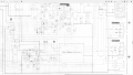
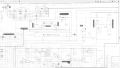
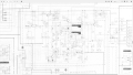
Please have a look at the schematic and the references below and see what you make of it. Much thx in advance!
REFS:
Manuals and schematics are here:
https://elektrotanya.com/hitachi_ha4700,ha3700.pdf/download.html
https://www.audioservicemanuals.com/h/hitachi/hitachi-ha/420953-hitachi-ha-4700-service-manual
https://gammaelectronics.xyz/sr_1981-10_ha4700.html
================
From Serv Manual:
HITACHI HA-4700/3700
DESCRIPTION OF THE NEW CIRCUIT
HA-4700/3700
Super linear circuit
The class B amplifier circuit is constructed as shown in Fig. 8. A constant idle current flows from the fixed bias circuit, Q3 and Q4 are alternately switched ON/ OFF corresponding to the input signal, and current flows to Load Ry. However, with this transistor, the response of the output current is delayed with respect to the base input current due to the time of the carrier storage at the base when this transistor changed from OFF to ON. As a result, it causes generation of switching distortion when the transistor changes from OFF to ON; the frequency increases as the signal frequency is higher.
So, a circuit which varies the conventionally fixed bias voltage according to the signal strength applies a constant bias voltage when there is no signal to prevent Q3 and Q4 from being set to OFF and prevent the generation of switching distortion has been installed.
The circuit surrounded by broken lines in Fig. 9 shows this bias circuit; this is called the super linear circuit.
In Fig. 9, the output neutral point (A) with non-signal is assumed to be the reference. When a positive signal is input, positive current flows to the load resistor Ry.
Voltage drop Ay occurs in RS and Ay gg, in Q3 by means of this current, the emitter (Base of Q3) voltage of Q1 becomes higher by Av + Ay gg compared with that during no signal and the base bias of Q5 becomes higher. When the base bias of Q5 becomes higher, the current increases, the voltage across R7 becomes higher, and the bias voltage of Q6 does not change compared with that of point (A). Accordingly, the base voltage of Q2 which is biased by Q6, Q8 and D2 is kept approximately the same as that during no signal, and the idle current continues to flow.
In the case of a negative signal, the reverse operation is performed keeping the base bias of Q1 constant. In the actual circuit, variable resistors are used for R2, R4 to adjust idle current, and in addition, a circuit which performs thermal compensation is installed.
LED power meter drive circuit 12 LEDs (HA-3700 7LEDs) per channel are used to indicate output level. These LEDs and driven by meter circuit; the relationship between the output level and the number of LEDs lit when 82 speakers are connected is as shown in Fig. 10. Incidentally, Fig. 11 shows the operation circuit.
Attachments
-
 479.1 KB Views: 0
-
 283.3 KB Views: 0
-
 254.1 KB Views: 0
-
 193.8 KB Views: 0
-
 191.1 KB Views: 0
-
 193.2 KB Views: 0
-
 289.7 KB Views: 0
-
 1.3 MB Views: 0
-
 1.1 MB Views: 0
-
 1.3 MB Views: 0