 Facebook
 Google
 GitHub
 Linkedin
Hello.
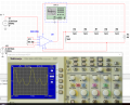
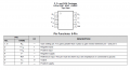
I am using an instrumentation amplifier INA126 and I am having some problems with it. The "real circuit" was not working properly so I am simulating the circuit that you can see in the picture using Multisim 14. This amplifier is going to be used to make an ecg circuit, it is a project for a college. But the thing is, we must power the amplifier using a 6V battery. I have used opamps in the past and powered then with a -V and a +V and it was ok, but never with a single supply. As you can see in the picture, the ina126 saturates, and I dont really understand why. You can see more about ina126 in the datasheet prints that I uploaded, such as gains and pin configuration.
Those 1k resistors where not all necessary. I was just trying to have a +5V (connected to pin 7), a 0V (which is the reference point, connected to pin 5) and a -1V (connected to pin 4) to power the amplifier, but it is not working, as it is saturating.
Hope my explanation wasnt very confusing
Thank you for your time
Attachments
-
 216.7 KB Views: 25
 -
 216.7 KB Views: 19
 -
 58.5 KB Views: 20
 -
 31.9 KB Views: 17


