Amplifier designing with 6 desired properties

Jony130

Joined Feb 17, 2009
5,600
This 470.0 is a potentiometer to set bias current for AB amplifier.
And voltage gain is equal to 22K/1K = 22 [V/V] = 26dB
 

Thread Starter

kmkl

Joined Dec 29, 2010
33
potentiometer is not allowed to use. i hope it be ok when i add ordinary resistor 470ohm instead of it.
 

Jony130

Joined Feb 17, 2009
5,600
Yes BD is medium power bjt. So you nedd to add real power BJT to achieve 20W.

For example you could replace BD stage with this output stage


I suggests use diagram C output stage
 

Thread Starter

kmkl

Joined Dec 29, 2010
33
is power accounted with the formula of avg(-I(R9)*Vout) ? (will 20w be ok with only these pwr bjts?)
where should i put the feedback resistor? serial to R4?
and, i am still in doubt that these two circuits will suply Ro<0.25ohm.
 

Audioguru

Joined Dec 20, 2007
11,248
is power accounted with the formula of avg(-I(R9)*Vout)?
P= I squared times R9 or V squared divided by R9 or V times I in R9.

(will 20w be ok with only these pwr bjts?)
Simply calculate the max current in the power transistors when the 4 ohm speaker has an output power of 20W then calculate the heating in the power transistors to see if they can withstand the heating when they have a suitable heatsink.

where should i put the feedback resistor? serial to R4?
First you must learn about what is negative feedback. Didn't you learn about it in school?? It is NOT in series with R9.
I am still in doubt that these two circuits will suply Ro<0.25ohm.
Most audio amplifiers have an output impedance of 0.04 ohms or less. 0.25 ohms is easy if you understand about negative feedback.
 

Audioguru

Joined Dec 20, 2007
11,248
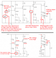
The gain is less than R6/R5= 20 times (its gain might be only 13) and you need a gain of 40dB which is 100 times.
The input level is shown at only 20mV (RMS?) so with a gain of 13 then the signal in the 8 ohm load is only 0.26V so the output power is only 0.26 squared/8= 8.5 milliwatts.

R9 needs to be bootstrapped so that its current doesn't drop to zero when it must supply plenty of current to turn transistor Q5 on. So the output swing is only about 9V p-p which makes a max power in the 8 ohm load of only 1.2W instead of the required 20W.

20W in an 8 ohm load is a signal of 12.56V RMS which is a swing of 35.8V p-p so the amplifier needs a supply of about 45V, not just 15V.

The supply voltage on your "changed" circuit is only 30V but its load is 4 ohms so its output might be 12W if so much power is not wasted in R10 and R11. Also with an input signal as low as only 20mV (RMS?) and a gain of 100 then the signal in the 4 ohm load is 2V and the power in the 4 ohm load is only 1W. Increase the input signal level.
 

Jony130

Joined Feb 17, 2009
5,600
R9 needs to be bootstrapped so that its current doesn't drop to zero when it must supply plenty of current to turn transistor Q5 on. So the output swing is only about 9V p-p which makes a max power in the 8 ohm load of only 1.2W instead of the required 20W.
I don't think that OP knows what bootstrap is.

20W in an 8 ohm load is a signal of 12.56V RMS which is a swing of 35.8V p-p so the amplifier needs a supply of about 45V, not just 15V.
I think you mean 12.85Vp not RMS
P = V^2/R ---> V = √(P*R) = 8.95V RMS.
For 12.56V an RL=4Ω you will get:
Pout = 12.56V^2 / ( 2 * RL) = 19.7W
 

Jony130

Joined Feb 17, 2009
5,600
No.
Real power is rated in RMS, not peak. Peak Power is Mickey Mouse Power. Peak power is double the real RMS power.
Ok I see you use RL=8Ω
But we can find real power knowing the peak voltage.
All we have to do is to use this equation:
P = Vp^2/ (2*RL)

kmkl


The Rin will be equal
Rin ≈ R1||R2 = 20KΩ

To find Rout I use PSpice because it is not so easy task to calculate Rout.
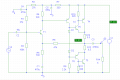
I use this circuit and ACsweep to plot Rout = V(V2:+) / I(V2)

14.PNG

Rout = 63mΩ=0.063Ω

As for output stage i use BD139/BD140 and BD441/BD442
But you can use BD185/186 and 2N3055/2955

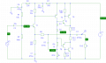
And here you have update version with Bootstrap and Rin=50K
15.PNG

And I forgot to add Miller compensation capacitor, but this is only PSpice project.
Because this amp in real life will blow up the output stage
 
Last edited:

Thread Starter

kmkl

Joined Dec 29, 2010
33
im adding what i got.

why do we use 2 stage power bjt?

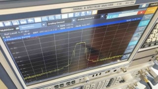
i thought that i can arrange cot off frequencies by changing capacitor's values. but there is a sharp pole at 10Hz which i couldnt remove.

still it satisfies me by the way it is. thank you :)
 

Attachments

Top