Amplifier circuit help (simple)

Thread Starter

ol'trusty

Joined Sep 9, 2009
48
HI guys
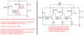
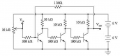
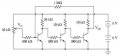
I Have just made this voltage amplifier to try and learn electronics.
It does not seem to be working for me.
Can someone please explain to me where Vin and Vout are suppose to be exactly ? I think that is my error.
Any other advice is very appreciated.
Thanks
Trusty
 

Attachments

Audioguru

Joined Dec 20, 2007
11,248
The base voltage of a transistor is low and the output voltage is supposed to be near half the supply voltage. So the base should have a voltage divider to reduce the input voltage.

But each transistor has a different amount of current gain and a different amount of base-emitter voltage and both change with temperature. So emitter resistors are used to reduce these differences.
 

Attachments

Thread Starter

ol'trusty

Joined Sep 9, 2009
48
Thank you for the responses! I didnt ask my question clearly and for that I am sorry. Where do I PLUG in the two wires for vin and vout ? Can you please show me on the schematic?
Thanks a lot
Trusty
 

Audioguru

Joined Dec 20, 2007
11,248
The slider of the 10k pot is your Vin. The transistors amplify its slider voltage which should be about +0.90V.
But the transistors are not biased correctly so they do not work properly.

The first and third transistors will be almost saturated and the second transistor will be almost cutoff when the pot is set so it works. But I think the amplifier will oscillate at a high frequency due to phase shifts.
 

Attachments

SgtWookie

Joined Jul 17, 2007
22,230
Like this:


See the lines with the circles at the end? Those are connection points; terminals.

Vin and Vout are in respect to ground.

[eta] Audioguru beat me to it.
 

Attachments

Top