Amplifier advice for digital cello with low output magnetic pickup

Another trick you can use to reduce the size and weight whilst maintaining SPL is to design a loudspeaker enclosure or baffle that fits in a corner (assuming corners are likely to be available). Maybe look at developing a flat-pack enclosure out of some sort of lightweight laminate e.g. Panels made from polystyrene sandwiched between thin sheets of plywood and held together with neodymium magnets, the enclosure would only need 5 sides as the base will always be formed by the floor on which it stands.
 

#12

Joined Nov 30, 2010
18,224
1.04ft3 Vented for F3 of 46Hz.
Gee it's nice to work with a person who: a) Has the brains needed to do this kind of work and: b) is willing to learn the rest of what he doesn't already know.

May I suggest carbon fiber and the utilization of curved shapes?
Carbon fiber is very strong (in comparison to its weight) and a curve is always stronger than a flat surface when hit with a compression wave in air.
 

Thread Starter

OnesAndZeroes

Joined Jan 19, 2017
25
Another trick you can use to reduce the size and weight whilst maintaining SPL is to design a loudspeaker enclosure or baffle that fits in a corner (assuming corners are likely to be available). Maybe look at developing a flat-pack enclosure out of some sort of lightweight laminate e.g. Panels made from polystyrene sandwiched between thin sheets of plywood and held together with neodymium magnets, the enclosure would only need 5 sides as the base will always be formed by the floor on which it stands.
Thank you for the additional trick. I'm thinking that I'm going to need all the tricks that I can get my hands on to make this sound good.

I was looking at the required vented volume for 8" drivers, and I'm afraid it will be too large for what I imagined.

So...I think I'm going to make my life difficult and try a 5" driver (W5-1611SAF) with an 8.9L cabinet (according to BandBox) and a 66Hz F3 with an SPL of 90dB.

For the power amp I'll try Dayton's 2x30w Class D along with #12's preamp schematic.

If the sound is not good enough I'll move to larger/heaver...but really I think I'll start losing inspiration once the thing gets too big.
 

Thread Starter

OnesAndZeroes

Joined Jan 19, 2017
25
Gee it's nice to work with a person who: a) Has the brains needed to do this kind of work and: b) is willing to learn the rest of what he doesn't already know.

May I suggest carbon fiber and the utilization of curved shapes?
Carbon fiber is very strong (in comparison to its weight) and a curve is always stronger than a flat surface when hit with a compression wave in air.
Haha...welll, if I do have some brains, what will really only matter is what I do with them. If I can't make this work, I guess I don't have enough. :)

Carbon fiber would be awesome! I'll try the wood approach first (I have a bunch of basswood lying around which might be cabinet worthy). If it's lacking I'll move forward on the difficulty chain. Hopefully...I don't have to go too far to get what I want (though I've always wanted to try building with carbon fiber).

Also...is there a recommended way to quantify cabinet response? I can borrow an oscilloscope...and maybe hook up a mic? Or just see what sounds good to my ears?
 

Alec_t

Joined Sep 17, 2013
15,149
Or just see what sounds good to my ears?
That is the ultimate test. Musicians seem to have special ears that can hear things an oscilloscope won't show :D. However, a 'scope could be useful for identifying obvious deficiencies (e.g. an unwanted resonance) wich could be overcome by damping or otherwise tweaking the enclosure properties. If you can't get access to a 'scope then you could record a mic signal and analyse it on a PC with e.g. Audacity.
 

#12

Joined Nov 30, 2010
18,224
I have seen a method with a calibrated microphone and a room that doesn't reflect sound. Anechoic chamber? Then a spectrum analyzer.
Seems like quite a job to build a room just to measure a sound. Every time I see that, I think about an open field where there is nothing to reflect sound, but there is always wind noise to contend with...then birds and sometimes cows. Did you know a bull can bellow from sunrise to sunset without getting a sore throat? I'm sure about the bellowing. I'm not sure about the sore throat.:D

I use a musician for my test room. Talk about golden ears! The designs that don't get complaints are designed for 23KHz. If I only design for 20 KHz, he will know it.
 

musiklab

Joined Jul 20, 2014
5
to get back to some nitty gritty: I believe that your pickup position is flawed.
If it is a coil wound around some magnets, the magnets should point at the strings, not lie horizontally /in parallel with them
so both the coils+magnets should be flipped 1/4 turn.
doing that may be a boost to the sound. It will probably also give you a lot more bass
look up wiki guitar magnetic pickup
 
Last edited:

#12

Joined Nov 30, 2010
18,224
I believe that your pickup position is flawed.
How can you tell the position of the pickups?

And while I'm here, a note for bloccos' suggestion. You can use low expanding spray foam in a structural sandwich. It's stickiness is incredible. I put some in behind a window sill for insulation and jammed the window sill into place so the foam wouldn't have to be trimmed later. When I came back to fasten the window sill, I couldn't get it out!!! It's still there, 28 years later, and still doesn't have any nails or screws.:p

If you want the opposite, Vaseline makes a good release agent for a non-porous surface like paint on a car (too oily) or paraffin (candle wax), but a rough surface will still be a problem getting it to release the foam.
 

Thread Starter

OnesAndZeroes

Joined Jan 19, 2017
25
to get back to some nitty gritty: I believe that your pickup position is flawed.
If it is a coil wound around some magnets, the magnets should point at the strings, not lie horizontally /in parallel with them
so both the coils+magnets should be flipped 1/4 turn.
doing that may be a boost to the sound. It will probably also give you a lot more bass
look up wiki guitar magnetic pickup
Yes, you're absolutely right. The magnets are oriented in a non-optimal way (signal strength wise).

I have a traditionally oriented pickup as well which I compare it to (about 30 mV AC RMS output for the traditional, versus 10mV AC RMS for mine) . I prefer the aesthetics of the non-optimal magnet orientation, but if I can't get the sound I want I'll go the traditional route.
 

Thread Starter

OnesAndZeroes

Joined Jan 19, 2017
25
How can you tell the position of the pickups?

And while I'm here, a note for bloccos' suggestion. You can use low expanding spray foam in a structural sandwich. It's stickiness is incredible. I put some in behind a window sill for insulation and jammed the window sill into place so the foam wouldn't have to be trimmed later. When I came back to fasten the window sill, I couldn't get it out!!! It's still there, 28 years later, and still doesn't have any nails or screws.:p

If you want the opposite, Vaseline makes a good release agent for a non-porous surface like paint on a car (too oily) or paraffin (candle wax), but a rough surface will still be a problem getting it to release the foam.
I'll think I'll try the non-sandwich approach first and see what kind of sound I can get. Good to have options though. :)

Also, my NTE 458 just arrived today. Will build the pre-amp shortly. :D
 
Last edited:

Thread Starter

OnesAndZeroes

Joined Jan 19, 2017
25
ps, the trick to that low noise pre-amp is that you pick an n-channel j-fet with at least 1 ma of Idss and trim it down to 1 ma by adjusting the resistor marked "220 ohms".
Well...the NTE 458 I ordered from Amazon arrived, but they actually sent a mislabeled diode instead. At least they refunded it without me even having to bother to return it.

Any recommendations on where to get the NTE 458? Or perhaps a replacement I can use instead?

I have some J201's laying around. Maybe I can try those?
 
Last edited:

#12

Joined Nov 30, 2010
18,224
The J201 is rated for 0.2 ma to 1 ma. I designed this for 1 ma for good battery life (440+ hours down to 7 volts) and a 3.3K drain resistor for a reasonable output impedance. You can use 0.5 ma or 2 ma because the signal arrives as millivolts and finishes up as tenths of a volt.
2N5457 Looks good at 1 ma to 5 ma.
It's so annoying to try to use a parametric search because the people who write them are incompetent.:mad:
http://www.mouser.com/Semiconductor...Z1yyteg2Z1yvvunvZ1z0w1gmZ1z0w1im&Ns=Pricing|0

Why am I not paying attention to anything except the Idss?
Because a j-fet is so capable in this position that they would probably commit suicide from being bored if they had any feelings.
If you need a lower impedance output, just run the j-fet at 2 ma or 5 ma and reduce the drain resistor value accordingly.
If you can only get 0.5 ma, you could increase the drain resistor accordingly, but it will still work perfectly for low voltage signals if you don't.
If you need a higher frequency range, change the drain capacitor. I tested the NTE458 to 200KHz and it had no difficulty at all.
These little things are tigers! Incredible input impedance, no base bias resistors to load down the input signal, some of them go all the way to radio frequencies, and you don't even need to consider what an op-amp does when it's over loaded or how to set up the power supply.

You just have to realize they are born, "on" and you quench their idle current down to the idle current you want with a source resistor and the gate connected below it. My design has rather low gain in the voltage department (15.8), but the impedance conversion is like 495K/3.3k= 150 to one. That's where the, "clean" comes from. The signal to noise ratio is undetectable and it will drive a 25 foot cord with no loss in the high frequencies if you reduce the drain capacitor to 2000 pf. You can also increase the gain if you want to. It's all there, one part at a time, if you understand which part does what.

The first capacitor (in conjunction with the 150K) sets the low frequency input limit. The drain capacitor sets the high frequency limit. The output capacitor sets the low frequency limit for the expected load. The 220 ohm resistor sets the idle current. The 150k resistor could be 50k or 500k and it will still work. The 1k resistor on the left can be shorted out for higher gain. That's what the 100 uf cap and the 1K pot are doing for adjustability. The 390k resistor is just an anti-click resistor for when you plug it in. See? Everybody has a job and they mostly don't interact.
 

Thread Starter

OnesAndZeroes

Joined Jan 19, 2017
25
The J201 is rated for 0.2 ma to 1 ma. I designed this for 1 ma for good battery life (440+ hours down to 7 volts) and a 3.3K drain resistor for a reasonable output impedance. You can use 0.5 ma or 2 ma because the signal arrives as millivolts and finishes up as tenths of a volt.
2N5457 Looks good at 1 ma to 5 ma.
It's so annoying to try to use a parametric search because the people who write them are incompetent.:mad:
http://www.mouser.com/Semiconductor...Z1yyteg2Z1yvvunvZ1z0w1gmZ1z0w1im&Ns=Pricing|0

Why am I not paying attention to anything except the Idss?
Because a j-fet is so capable in this position that they would probably commit suicide from being bored if they had any feelings.
If you need a lower impedance output, just run the j-fet at 2 ma or 5 ma and reduce the drain resistor value accordingly.
If you can only get 0.5 ma, you could increase the drain resistor accordingly, but it will still work perfectly for low voltage signals if you don't.
If you need a higher frequency range, change the drain capacitor. I tested the NTE458 to 200KHz and it had no difficulty at all.
These little things are tigers! Incredible input impedance, no base bias resistors to load down the input signal, some of them go all the way to radio frequencies, and you don't even need to consider what an op-amp does when it's over loaded or how to set up the power supply.

You just have to realize they are born, "on" and you quench their idle current down to the idle current you want with a source resistor and the gate connected below it. My design has rather low gain in the voltage department (15.8), but the impedance conversion is like 495K/3.3k= 150 to one. That's where the, "clean" comes from. The signal to noise ratio is undetectable and it will drive a 25 foot cord with no loss in the high frequencies if you reduce the drain capacitor to 2000 pf. You can also increase the gain if you want to. It's all there, one part at a time, if you understand which part does what.

The first capacitor (in conjunction with the 150K) sets the low frequency input limit. The drain capacitor sets the high frequency limit. The output capacitor sets the low frequency limit for the expected load. The 220 ohm resistor sets the idle current. The 150k resistor could be 50k or 500k and it will still work. The 1k resistor on the left can be shorted out for higher gain. That's what the 100 uf cap and the 1K pot are doing for adjustability. The 390k resistor is just an anti-click resistor for when you plug it in. See? Everybody has a job and they mostly don't interact.
Thank for for this response. When I first read it I had very little idea what you were talking about...but it inspired me to learn. :)

I found a tutorial on biasing J-Fets here which helped me understand (some of) what you wrote: http://diy.smallbearelec.com/HowTos/BreadboardBareAss/BreadboardBareAss.htm

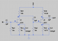
I wound up using two J201's I had on hand (as I wasn't patient enough to wait for a replacement for the NTE458). Here's the circuit I used (biased specifically for the J201's I had on hand). I wound up using 1000uF source caps as it seemed to result in less loss on the low end.

two j201 preamp.png

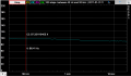
The circuit yields about 40dB gain (97x) on the low end and a Bode plot (without load) here:

bode.png

I'm not sure how clean the pre-amp is as it's currently on a breadboard and wires are going everywhere, so I'm picking up a nearby radio station as well. Any tips on reducing radio interface would be helpful. Also, I'm seeing a consistent high pitched whine once amplified which I would like to reduce as well.

I'm sending the output from the pre-amp to a Dayton Audio KAB-230 2x30W Class D Audio which drives a Dayton Audio ND105 4" 8ohm speaker. Plus for the KAB-230 is that it receives Bluetooth as well.

I'm very happy with the volume/sound coming out of the setup. With the amp turned up all the way I get volume from the instrument that's painful to listen to (won't usually be there but good to have). Starts to distort about 85% of the way up...which is fine. The volume approaches my real cello even at 85% amp, even though the speaker box right now is definitely not ideal (9x6x2" with pieces of wood just taped together...does include a passive radiator though).

My goal at this point is to get the interference cleaned up. I'll try building a tight version of the pre-amp. I expect it will help, but it's entirely likely that my homemade humbucker pickup (with 10k turns on each pickup) is picking up more than just string vibration.
 
Last edited:

#12

Joined Nov 30, 2010
18,224
It's the incredibly high input impedance that is allowing radio stations to be picked up. Change RG1 and RG2 to about 100k.
Then put capacitors in parallel with RD1 and RD2 so the j-fets don't amplify in the radio frequency range.
568 pf will limit stage 1 to 20 KHz and 474 pf will limit stage 2 to 20 KHz.
Your source capacitors are way too big at 1000 uf. They would work according to my calculations at 47 uf.
Then put it all in a metal box, like an Altoids tin. You can't have a gain of 100 laying out in the open without it picking up everything from fluorescent lights to AM radio.
 

Thread Starter

OnesAndZeroes

Joined Jan 19, 2017
25
It's the incredibly high input impedance that is allowing radio stations to be picked up. Change RG1 and RG2 to about 100k.
Then put capacitors in parallel with RD1 and RD2 so the j-fets don't amplify in the radio frequency range.
568 pf will limit stage 1 to 20 KHz and 474 pf will limit stage 2 to 20 KHz.
Your source capacitors are way too big at 1000 uf. They would work according to my calculations at 47 uf.
Then put it all in a metal box, like an Altoids tin. You can't have a gain of 100 laying out in the open without it picking up everything from fluorescent lights to AM radio.
Thank you for the suggestions. I have reduced RD1/RD2 to 100k and reduced the source capacitors to 100uf (didn't have any 47's on hand).

This has basically removed the issue with the radio interference. Thank you.

When trying to filter out the high pitched whine with the capacitors, I find that adding a capacitor in parallel to RD2 gives me excellent (but undesired) radio reception.

I was thinking that the high pitched interference was perhaps caused by the development board I'm using (which includes a built-in 9V power supply). So...I tried to disconnect it and use just a 9V battery to power the pre-amp. Unfortunately when I do I get an extremely high pitched whine from the pre-amp (or amp) and no output to the speakers at all (that I can hear).

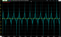
Checking the pre-amp output on an oscilloscope looks like the following and is unaffected by instrument signal. When the pre-amp was powered previously by the development board I could see the amplified audio signal here (even when the pre-amp was hooked up to the amp).

unknown.png
 

#12

Joined Nov 30, 2010
18,224
That nasty oscillation should clear up when you make a nice, tight circuit board. Temporary boards have capacitance between connectors and the wires hanging in the air are radiators. Clean up the layout and the oscillations should stop. At that point, drain capacitors will work as they should by limiting the high frequency gain to the audio range.
 

#12

Joined Nov 30, 2010
18,224
Musicians seem to have special ears that can hear things an oscilloscope won't show :D.
That is an absolute. I don't care what the scope shows, no amplifier leaves my shop until I play a guitar through it.
I call it the human test. A scope will not show a spotty volume control or a loose tube socket.
 

Thread Starter

OnesAndZeroes

Joined Jan 19, 2017
25
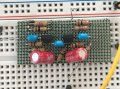
That nasty oscillation should clear up when you make a nice, tight circuit board.
Built the cleaned up board and the signal is much cleaner now. :)
IMG_3311.JPG

That said I believe that I am going to have to bite the bullet and redo the pickup.

The pickup is producing less than ideal signal (due to my incorrect orientation the magnets I suppose) and though it's a humbucker it is still producing a hum as well (I guess the two coils are not perfectly balanced). Maybe not a lot of hum...but when pre-amped with 90x gain...it's too much.

Might as well make my life easier and start with a proper signal. Then I'll be able to cut the gain some on the pre-amp as well.

I think I'm going to create an optical pickup. I had some LTR-4206 phototransitors lying around and paired one up with a white LED on the opposite side of a string. Put that through the 90 gain pre-amp. To my amazement it worked the first time I tried it. Much cleaner/stronger signal than the pickup for sure. Maybe I'm actually learning something. :)
 

#12

Joined Nov 30, 2010
18,224
balancing a humbucker.png
Here's an idea:
The basic principle of a humbucker is the same principle as strapping two microphones together, out of phase. They pick up far field noise equally and near field energy differently. This idea might not work, but it's worth a try.

ps, When you connect the humbuckers to the amplifier, they provide the DC path to ground that you were using a 3M resistor for. There is no DC voltage in the pickups, so you don't need an input capacitor at all. If it's all going to be always connected, you can eliminate a couple of parts. If you want to hold the amplifier separately and plug it in, you will still need the 100K resistor to ground the gate or the amplifier will go crazy picking up radio and fluorescent lights.
 
Last edited:

Thread Starter

OnesAndZeroes

Joined Jan 19, 2017
25
View attachment 119819
Here's an idea:
The basic principle of a humbucker is the same principle as strapping two microphones together, out of phase. They pick up far field noise equally and near field energy differently. This idea might not work, but it's worth a try.

ps, When you connect the humbuckers to the amplifier, they provide the DC path to ground that you were using a 3M resistor for. There is no DC voltage in the pickups, so you don't need an input capacitor at all. If it's all going to be always connected, you can eliminate a couple of parts. If you want to hold the amplifier separately and plug it in, you will still need the 100K resistor to ground the gate or the amplifier will go crazy picking up radio and fluorescent lights.
A couple questions about the the diagram. What do the 47k resistors do?

I have the pickups wired similarly (each one the opposite of the other), but don't include anything like the 47k resistors. They just connect directly to the pre-amp.

Also, what do the two circles in the diagram mean?
 
Top