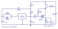
C5 provides an RF path to ground to the bottom of the tuned circut and allows R3 to provide positive bias to pin 2 of the coil via L1. C2 filters out any remaining RF in the demodulated signal. Q1 is turned partly on by the current flowing through R4.
C5 provides an RF path to ground to the bottom of the tuned circut and allows R3 to provide positive bias to pin 2 og the coil via L1. C2 filters out any remaining RF in the demodulated signal. Q1 is turned partly on by the current frowwing through R4.
That bias method will work with the emitter connected directly to GND.
The capacitor is as you say; to bypass the emitter resistor to AC - negative feedback would cancel most of the transistor's gain without it.
The emitter resistor is usually used with the text book self compensating common emitter stage - you'd have 2 series resistors as a voltage divider feeding the base, the base voltage minus Vbe combined with the value of the emitter resistor sets the(theoretically possible) collector current.
Hmm. But why do we need radio path to ground through capacitor? We tune the circuit by changing variable capacitor in tank circuit and pass the current through the IC but what is the point of C5? What would it change to the circuit? I am also confused why we use parralel tune circuit instead of series because at resonant frequency we have lowest current and highest voltage? i did expect to be opposite because we need highest current?
Hmm. But why do we need radio path to ground through capacitor? We tune the circuit by changing variable capacitor in tank circuit and pass the current through the IC but what is the point of C5? What would it change to the circuit? I am also confused why we use parralel tune circuit instead of series because at resonant frequency we have lowest current and highest voltage? i did expect to be opposite because we need highest current?
You don't - the transistor only amplifies audio, that requires a bigger capacitor than Rf.
Without a bypass capacitor across the emitter resistor; it would behave partially as an emitter follower, the voltage developed across the emitter resistor would cancel out most of the signal applied to the base.
With the full text book self compensating emitter follower; the DC component across the emitter resistor cancels out changes in current due to temperature related gain variation - its also part of the design process to obtain a stable predictable gain stage for any gain spread for the transistor type.
Emitter current sensing is irrelevant for the C/B resistor bias arrangement.
Also consider that the current into C5 serves not only to bias the input but also the feedback that is required for the automatic gain control function (the grearer the current, the higher the gain, so C5 and R3 function as a low pass filter for the AGC
The two ends of the tuned circuit are the source of the signal . (I assume the inductor is wound on a ferrite rod to work as the antenna as there is no connection to an external antenna.) IC1 needs to see it's input signal between pins 1 ans 2. I will try to explain it in DC terms. Consider that the input to IC1 can be represented by a 1K resistor. Think of a battery (Say 1.5V) in place of the tuned circuit with it's + end connected to pin 2 of the IC. If the negative end of the battery was not connected to anything then there would be no current through the 1K resistor so no voltage across it. If the negative end of the battery was connected to pin 1 by a 100K resistor then the voltage across the 1 K resistor would be 1.5 x 1000/101000) = 0.0148 volts If we assume the input frequency is 1 Mhz then the 0.01 uF capacitor would have a reactance of about 16 ohms. Going back to the example using DC then if we connect the negative end of the battery to pin 1 via a 16 ohm resistance then the voltage across the 1 K resistor will be 1.5 x 1000/1016 = 1.47 volts. So you can see we get a much bigger input to the IC.
The two ends of the tuned circuit are the source of the signal . (I assume the inductor is wound on a ferrite rod to work as the antenna as there is no connection to an external antenna.) IC1 needs to see it's input signal between pins 1 ans 2. I will try to explain it in DC terms. Consider that the input to IC1 can be represented by a 1K resistor. Think of a battery (Say 1.5V) in place of the tuned circuit with it's + end connected to pin 2 of the IC. If the negative end of the battery was not connected to anything then there would be no current through the 1K resistor so no voltage across it. If the negative end of the battery was connected to pin 1 by a 100K resistor then the voltage across the 1 K resistor would be 1.5 x 1000/101000) = 0.0148 volts If we assume the input frequency is 1 Mhz then the 0.01 uF capacitor would have a reactance of about 16 ohms. Going back to the example using DC then if we connect the negative end of the battery to pin 1 via a 16 ohm resistance then the voltage across the 1 K resistor will be 1.5 x 1000/1016 = 1.47 volts. So you can see we get a much bigger input to the IC.
But if we didn't have the capacitor we wouldnt have any resistance so we should have higher signal wouldn't we? (1k ohm as you mentioned )So lets say to catch some music with my radio circuit. The signal travelling through the air is already modulated signal? We change the capacitor value to find the required resonant frequency and catch that radio stop. And then we send it throught the IC to amplify the signal. But still not sure what is the main purpose of C5? Is it here to ground unwanted too high frequencies?
(Note from moderator, when quoting another post, be careful to put your reply outside the quoted area. -dc)
Also consider that the current into C5 serves not only to bias the input but also the feedback that is required for the automatic gain control function (the grearer the current, the higher the gain, so C5 and R3 function as a low pass filter for the AGC
With the single bias resistor shown; automatic gain is accomplished by a fall in collector voltage resulting in less current flowing to the base via the base resistor.
With an emitter resistor; the base bias is not referenced to GND. The emitter resistor usually isn't present with that bias arrangement.
I think this statement is true for in the case of the transistors in the RF amplification stage of the MK484.
EDIT: @ian field is correct...again! Reviewing the ZN414 and MK484 datasheets the 100k resistor is only there for bias. AGC is a function of the resistor in series with the battery.
 Facebook
 Google
 GitHub
 Linkedin
 18.6 KB Views: 53


