 Facebook
 Google
 GitHub
 Linkedin
Hi everyone this is not homework but I'd appreciate some help,
I am looking through the notes on the following link http://www.allaboutcircuits.com/textbook/digital/chpt-3/cmos-gate-circuitry/.
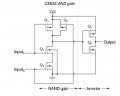
Does anybody have a truth table for the CMOS AND gate circuit with the inverter (Image attached) so i can see how the inverter behaves?
I am looking to see how Q5, Q6 would function and the output from each state.
Thanks
I am looking through the notes on the following link http://www.allaboutcircuits.com/textbook/digital/chpt-3/cmos-gate-circuitry/.
Does anybody have a truth table for the CMOS AND gate circuit with the inverter (Image attached) so i can see how the inverter behaves?
I am looking to see how Q5, Q6 would function and the output from each state.
Thanks
Attachments
-
 18.1 KB Views: 11


