AKG SR450 - Used wrong type of current power supply - wont turn on

Thread Starter

markoskerass

Joined May 11, 2017
8
Hello.
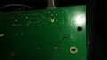
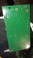
I have the wireless microphone receiver at the title and I connected a wrong power supply to it. It had same specs, 12v 1A but it was AC instead of DC and now the device wont turn on! Is there any fix/workaround to make the receiver work again? I tried plugging in the original DC power supply but no response whatsoever from the device.
Thanks!
 

R!f@@

Joined Apr 2, 2009
10,004
Welcome to AAC.

We are not psychics.
We cannot repair things we cannot see.
How about posting pictures of your item
 

mcgyvr

Joined Oct 15, 2009
5,394
Just so its clear.. You used a 12VAC power supply on a device intended to be fed from 12VDC power supply?
Can you get a picture thats more in focus?
 

dl324

Joined Mar 30, 2015
18,216
If you need more pictures of something specific let me know. I took it apart completely.
http://imgur.com/a/Nke2X
It would be helpful if you posted images with an appropriate resolution on this site. The link you provided is slow for me.
tmp1.jpg
From what I can see, the supply goes through a resistor and diode, so nothing got reverse biased.

It would be helpful if you could locate a schematic or trace the power supply section of the board.

The soldering of the power leads looks like it was done by someone who didn't know what they were doing...
 

Thread Starter

markoskerass

Joined May 11, 2017
8
Cant seem to find any schematic for the board. I contacted AKG but I'll probably get no positive response since I'm years out of warranty. I'm new to this whole thing so I dont even know where to start from.
 

Tonyr1084

Joined Sep 24, 2015
9,744
I know I'd really love to see a better view of the wires and the traces hidden beneath the gunk.

I've seen reverse protection diodes used to prevent hooking up backwards to the power supply. Usually in that case they're meant to burn out a trace on the board. I'm only seeing one side of the board and am wondering what might be going on with the other side of the board at that location. But from here it's really hard to tell what's going on. You COULD test the diode to see if it has been blown open. Test it with a multimeter set on diode check. One way the diode should read open and the other way should read around 0.450; something reasonably close to that, say within ±0.100.

That's where I'd start. THEN I'd connect the correct power supply and start tracing out voltages. Make sure they're going where they're supposed to go. Would be a great help if you had the schematic, but if not - following the traces on the board as best you can. However, two layer boards are a bugger to trace, and multi-layer boards are just about impossible to visually trace out.
 

Thread Starter

markoskerass

Joined May 11, 2017
8
I know I'd really love to see a better view of the wires and the traces hidden beneath the gunk.

I've seen reverse protection diodes used to prevent hooking up backwards to the power supply. Usually in that case they're meant to burn out a trace on the board. I'm only seeing one side of the board and am wondering what might be going on with the other side of the board at that location. But from here it's really hard to tell what's going on. You COULD test the diode to see if it has been blown open. Test it with a multimeter set on diode check. One way the diode should read open and the other way should read around 0.450; something reasonably close to that, say within ±0.100.

That's where I'd start. THEN I'd connect the correct power supply and start tracing out voltages. Make sure they're going where they're supposed to go. Would be a great help if you had the schematic, but if not - following the traces on the board as best you can. However, two layer boards are a bugger to trace, and multi-layer boards are just about impossible to visually trace out.
Thanks! I checked the diode and it gave me the readings you said. 453 one way and open the other way. I'm following the traces as we speak, but I think I'm missing something. Will investigate further...
 

Tonyr1084

Joined Sep 24, 2015
9,744
I recently had a GFCI outlet go bad. Went bad after 3 months use. Just shut down and would not reset. Checked the wiring and everything was up to code and connected properly. Contacted EATON (manufacture of the GFCI outlet) but they told me to contact the store where I purchased it. Store said "Contact EATON." Frustrated with the lack of direction I sent an e-mail. They said "Contact the store where you bought it." Ever more frustrated I just decided I was going to scrap the thing and open it up. Found a blown transistor (SMD). The transistor had exploded part of the body away from the board. Easy to find. Could have soft-blown and no amount of visual would have revealed anything. The moral of this story is: You won't always see what's wrong. Sometimes you have to inject a signal to follow something from one point to another.

And with your board, it appears it is likely a multi-layer board. I seriously doubt you're going to be able to follow any traces with any kind of confidence you know all the places it goes. But good luck. Hopefully you can find the problem.
 

dl324

Joined Mar 30, 2015
18,216
This is the other side of the board.
It's virtually impossible for anyone to trace the circuitry from the photos you posted.

It would be best if you applied power to the board and verified that the power supply circuitry, if any, is functioning. If you want advice from this forum, we need a schematic.
 

Thread Starter

markoskerass

Joined May 11, 2017
8
Hi again. I've been trying to reach AKG this whole time but they haven't replied yet. Their support is terrible, i've contacted them in the past. I've kinda given up on this project since my electronics knowledge is really limited.
 

Tonyr1084

Joined Sep 24, 2015
9,744
Something went reverse current. Likely something blew out - even if you can't see any damage, something smoked the stogie. And usually when something like that happens it tends to take down a whole lot of other stuff with it. A properly protected board should either blow out a fuse or burn a trace on the board. Unfortunately none of us are going to be able to give you much advice without a schematic. And since two things are likely 1) a host of things have burned out & 2) you're probably not going to get the schematic from AKG; then I'd suggest this project becomes a source of scrap parts for other things.

Sorry we can't give you better news.
 
Top