Advice on LED Stairwell Lighting

Thread Starter

>Chris<

Joined Oct 16, 2008
17
Alright, after completely dropping this project before, I decided to get back to it :D
For now I dropped the idea of dimming the LEDs and I'll get to that when it is working the way I want it to.
So I want the steps to be lit one after the other with a small delay in between each of them and then turn off the same way when you get off the stairs.

Since I know C and Assembly Language now, I started programming it in C for an Atmel Atmega8515 uC. I worked with that chip before and it has 35 I/O pins so I could use it on pretty big staircases too. I ran into some problems concerning the input though.

I would need sensors on the top and bottom of the stairs. I was thinking about IR sensors but I'm not sure if they would work the way I want.
Since I already thought about all the errors I could get if there are 2 people going down the stairs or 1 going up and then another one going down at the same time, I thought about using 2 sensors on the top and 2 sensors on the bottom. Depending which of the sensors is activated first, I would know which direction a person is going and therefore eliminate all the errors that could occur.
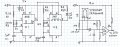
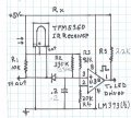
From the research I did it looks like IR sensors are not really focused on a specific point, so I thought about using 2 lasers for this instead. For the lasers I'm not too sure about what kind of receiver I would need though. I couldn't find much on that. In a video I saw that a guy was using a laserpointer and an IR receiver. Would that work? I guess it would depend on the wavelength right?

So with this setup I could constantly check the 4 inputs and depending on which one of them goes high, due to a broken beam, I could turn the lights on or off. I just have to figure out now how exactly to handle the inputs in the program but that shouldn't be a problem.

So what do you guys think? Any ideas on the sensors?
 

Bernard

Joined Aug 7, 2008
5,784
A laser pointer can trigger a wide variety of light sensors, but if not modulated with proper frequency,[ some @ 38 kHz ], will not work with popular IR code receivers. Still my favorite scheme is the one from Markd77, a beam break on every step illuminating the one before, tripped, & one next, with a fade out. Might be about US $ 1.00 excluding the illuminating LED, per step. If you are still with us, I'll breadboard a simple ckt drawn up while on convention trip, just got back tonight.
 

Thread Starter

>Chris<

Joined Oct 16, 2008
17
Hi Bernard,
I finished writing the program and I successfully simulated it in AVR Studio. I wrote it to work with 4 inputs and to be low-active.
So I was thinking I could actually use IR transmitters and receivers and just use on transmitter for 2 receivers. The stairs aren't very wide so I think an IR transmitter could do it. Is there a way I can calculate the range of these transmitters?
Having 3 steps turn on for every step seems like a nice idea too but I already wrote the code to have them all turn on, one after another. :)
I left out the fading though, because it would have been a lot harder to include the pwm in the code. Especially since I used C and you can't really tell how many cycles the instructions need.

I would still like to see your idea though!
Thanks for the input!
 

Bernard

Joined Aug 7, 2008
5,784
On your question , " one transmitter for two receivers" , yes it can be done with a laser pointer but with a cylinder plano convex lens to stretch the dot to a line. The one I have is 5.9 mm focal length, mutch to short but works well at 10 ft using photo transistor. Without lens detection was greater than 100 yds. Lens might be available from Anchor Optics. Using 25mA, 20 deg IR LED range about 2 cm.
 

Thread Starter

>Chris<

Joined Oct 16, 2008
17
On your question , " one transmitter for two receivers" , yes it can be done with a laser pointer but with a cylinder plano convex lens to stretch the dot to a line.
I'm sorry I meant IR LED instead of the Laser. But if your saying that I can only get 2cm at 25mA I guess I'm not getting around the Lasers then.
 

Bernard

Joined Aug 7, 2008
5,784
2 cm is not a limit, just not right parts for your project; just look at TV romote range. I believe they use 200 mA or more, pulsed & IR receiver has internal filtering & amplification. Could use some help here.
 

Bernard

Joined Aug 7, 2008
5,784
Possibly some better parts: IR emitter, TSAL6400, @ $.50, pulsed at 300mA range stated as 35 meters, using TFM5360 IR receiver @ 5/ $ 1.00. RS has a better receiver @ more cost. I believe both are Vishy.
 

Thread Starter

>Chris<

Joined Oct 16, 2008
17
Thanks for the replies Bernard!
What do you mean with Vishy? Or did you mean Fishy? :D
Those parts look pretty good though. It would definitely be cheaper than the laser stuff and also invisible!
I have another question though.
If I have a maximum output of 40mA on each pin of the Chip, would I just take the total amount of pins that are going to be connected in order know what kind of power supply I need to run this?
I mean just for the chip. For the transmitters I'll have to design a driver I guess so I can get it pulsed at 300mA.
 

Bernard

Joined Aug 7, 2008
5,784
Progress rpt: Now that I see you are still with us, Chris. I bread boarded the 36 kHz pulsed IR LED transmitter. Strange results, detection with TMF5360 worked fine- even with IR LED removed, added more power de coupling to no avail; seperated Tx & Rx by 4 ft & used seperate power supplies. Still would see around small bolckages untill LED current was reduced to 13 mA. Tuning is quite broad. Current drain - just two 555 unloader oscillators; 20 % duty on 36K Hz, 10% on pulser, so about 2% at 13mA for IR LED. Have you picked out illuminating LEDs yet ?
 

Thread Starter

>Chris<

Joined Oct 16, 2008
17
Hey Bernard thanks a lot for your help!
I am on vacation for a couple more weeks right now, so I can't test anything until I'm back home. Well except for my code which I wrote and tested with AVR Studio.
I think I still have 5mm White LEDs at home rated 3.8-4.5V,20mA. I could get different ones though.
So but your saying when you ran the LED with 13mA it worked without problems? Also, how did you decide to use a 20% DC?
 

Bernard

Joined Aug 7, 2008
5,784
Rx not tested yet, but 1 st out can feed a μP, which can detect missing pulse & control LED drivers? Receiving angle is rather broad, about +- 50 deg. @ 3 ft.; straight on range is 15 ft. 20 % DC? seemed like a good idea at the time, was to save power. U1 gives 10 PPS @ about 10% DC. R3 was a 30k pot in series with 2k. IR LED same one that gave 2 cm before.
 

Attachments

Last edited:

Thread Starter

>Chris<

Joined Oct 16, 2008
17
Ok I have some questions about the schematic. What exactly does the cascading of the 555 timers do? So you are resetting the 2nd one every 10Hz but how does that change anything? Also, from my calculations the second timer is running at around 47kHz. Doesn't the receiver work with 36?
The LED driver has to be controlled by the uC since I need to check if both receivers have been passed to turn the LEDs on/off.
Finally, can I use another 555 timer on the receiver as a missing pulse detector? Because I think building a detector with components is a lot easier than with a uP. Or I would have to use another chip, because I wrote my program in C and its impossible to check for missing pulses with that on the same chip.
 

Bernard

Joined Aug 7, 2008
5,784
You are suposed to be enjoying your vacation-- but it is nice to hear from you. With a continuous tranmission , receiver stays hi, with interuption- still hi, pulsing seems to work. I was surprised at pot low reading, measured frequency is 33 kHz,; the tuning is quite broad. The missing pulse -receiver is not finished yet. Programming or μC are not in my inventory, last programming was FORTRAN 4 introduction about 1962.
 

Thread Starter

>Chris<

Joined Oct 16, 2008
17
Well it is not a real vacation in that sense. I am waiting for my new immigration papers so I can go back to Canada. It felt like vacation in the beginning but now I'm just waiting so I'm spending my time working on circuits :D
With a continuous tranmission , receiver stays hi, with interuption- still hi, pulsing seems to work.
Does that mean that even with the pulsing it sends out a continuous hi?

I made a simple block diagram to illustrate how I thought I would structure the whole circuit.
There is the IR transmitter/receiver part with their needed circuitry. This part I need twice. Then the outputs of the 4 receivers goes into a detector, which is interfaced to the uC. Then the uC takes care of the LEDs. From what I read I can drive the LEDs directly with the uC, which can output up to 40mA on each pin. If this doesn't work though I will need to put some kind of driver for the LEDs.
I will just try it out and see if it works I think.

Programming or μC are not in my inventory, last programming was FORTRAN 4 introduction about 1962.
Wow thats a bit before my time :D The problem with C is though, that you can't tell how many cycles an instruction takes. For that I would have to use assembly language, which I also learned. But thats a lot harder to program and my program is already in C so a separate circuit is the easiest way.
 

Attachments

Bernard

Joined Aug 7, 2008
5,784
Added pin # to Rx. Left off 3 sec delay as not needer with your set-up. Note- if beam remains blocked, output stays hi. Still think two IR sources would be better, just put two in series seperated, and shange R5 to about 75Ω. Limit beam width with shielding. Have fun.
 

Attachments

Thread Starter

>Chris<

Joined Oct 16, 2008
17
Thanks!
I would really appreciate though if you could let me know why you are cascading the two 555 timers. I don't really understand that.
 
Top