Facebook
 Google
 GitHub
 Linkedin
Hello everyone!
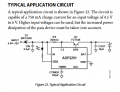
Im designing a battery charger circuit with ADP2291. You can see the datasheet in this link.
https://www.analog.com/media/en/technical-documentation/data-sheets/ADP2291.pdf
Normally this circuit should work like this. When you choose RS=200mohm you have to get Imax=750mA (Changing between Vin=4.5-12V). And when you choose RS=100mohm you have to get Imax=1.5A.(Changing between Vin=4.5-12V)
Here are my inputs,
-Vin=5V Radj=open Vrs=70-100-130mV RS=100mohm&200mohm (i tried different ways)
-My battery voltage between 3-4.2V. Not less than 3V and not equal or higher than 4.2V. (I also tried the battery for is it healthy.)
My outputs like this,
-Vadj=3V Vout=4.2V (stabile)
-Icircuit= 243mA and Ibat=230mA
I exactly set the figure.23 and figure.24 from datasheet. I also tried lots of different way. But I couldnt find the answer. Can anyone help me about ADP2291 or why its not working healthy?