adjusting the output current of a constant current LED psu

Thread Starter

prometei

Joined Apr 13, 2008
98
Hi,

I just wanted to provide some idea what you might have there even if not exact. A place to start thinking.

I still dont see any capacitor between D and S of the mosfet though, and that is almost never done because that puts a lot of stress on the mosfet when it turns on. That cap may not last very long either if the mosfet survives that is. I guess you got the part number for the mosfet from the part itself, but where did you get the idea that the cap from D to S is really a capacitor and not some other part like transient suppressor or something.
I assumed it's a cap cause it looks like one and there is a marking on the pcb "c8", plus I've measured the capacitance (in circuit) = 0.45uF
 

MrAl

Joined Jun 17, 2014
13,765
I assumed it's a cap cause it looks like one and there is a marking on the pcb "c8", plus I've measured the capacitance (in circuit) = 0.45uF
Hi,

Wow, that's a big cap to put across a MOSFET D S unless maybe the mosfet is operating in the linear mode.
Do some math. Figure how much current will flow through that cap when the mosfet turns on, if it is operating in the switch mode. It is going to be high.
The only other thing is maybe it's not really a mosfet, but a mosfet would be typical for that kind of circuit.
Well, another possibility of course is that the designer was not an expert in power supply design technology. No expert I've ever known in the past would ever put a cap there, even a much smaller one, in switch mode operation, and I have actually talked to an engineer about this and he was the chief engineer at the time. In linear mode however it may be even typical for some designs.
In a lot of circuits a snubber is used as you probably know. They use a capacitor also, but the current is restricted with a diode for when the mosfet turns OFF so the cap can absorb the spike energy. Some way of discharging the cap is then employed, and it could be with the same mosfet in some cases, but it will not be a direct short it would be through a resistor.
This is a mystery.
Is there any stampings on the board under the mosfet like with the 'cap' ?
 
Last edited:

Dodgydave

Joined Jun 22, 2012
11,395
I had that idea because my LED psu has a similar low V circuit. The only thing connecting the low and hig V sides is the blue CY4 component as shown in the attached pics

What is the number of the chip pulsing the Mosfet, as that will be controlling the current?
 

Thread Starter

prometei

Joined Apr 13, 2008
98
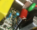
ok, I think I've got it. On the attached pic there is a blue resistor, ca. 2.5 ohm, wired in parallel with two 0.75ohm smd resistors. One end goes to the pin of the 0H-A26 IC and the other to the source of the mosfet. I've removed the blue 2.5 ohm resistor and the output of the PSU dropped from the ca. 900mA to 700mA, so I'm pretty sure this is the sensing resistor(s). Not sure why the manufacturer used a combination of resistors instead of just using one, perhaps for precision, or?

Would it be ok to place a small value potentiometer in series with the remaining 0.75ohm smd resistors, for current adjustment?
 

Attachments

Dodgydave

Joined Jun 22, 2012
11,395
ok, I think I've got it. On the attached pic there is a blue resistor, ca. 2.5 ohm, wired in parallel with two 0.75ohm smd resistors. One end goes to the pin of the 0H-A26 IC and the other to the source of the mosfet. I've removed the blue 2.5 ohm resistor and the output of the PSU dropped from the ca. 900mA to 700mA, so I'm pretty sure this is the sensing resistor(s). Not sure why the manufacturer used a combination of resistors instead of just using one, perhaps for precision, or?

Would it be ok to place a small value potentiometer in series with the remaining 0.75ohm smd resistors, for current adjustment?

Yes you can put a potentiometer in series, but the voltage across the resistors is about 300mV, so even a 1 ohm preset will give you 300mA, 2 ohms 150 mA etc, I would just choose what current you need and fix it with a resistor.
 

MrAl

Joined Jun 17, 2014
13,765
ok, I think I've got it. On the attached pic there is a blue resistor, ca. 2.5 ohm, wired in parallel with two 0.75ohm smd resistors. One end goes to the pin of the 0H-A26 IC and the other to the source of the mosfet. I've removed the blue 2.5 ohm resistor and the output of the PSU dropped from the ca. 900mA to 700mA, so I'm pretty sure this is the sensing resistor(s). Not sure why the manufacturer used a combination of resistors instead of just using one, perhaps for precision, or?

Would it be ok to place a small value potentiometer in series with the remaining 0.75ohm smd resistors, for current adjustment?
What value did you have in mind?

Might have to be careful not to open circuit the output.
 

Thread Starter

prometei

Joined Apr 13, 2008
98
What value did you have in mind?

Might have to be careful not to open circuit the output.
Not sure what value yet, but it should not matter since it's in series with the two 0.75 resistors. I might just leave it the way it is at 700ma
 

MrAl

Joined Jun 17, 2014
13,765
Not sure what value yet, but it should not matter since it's in series with the two 0.75 resistors. I might just leave it the way it is at 700ma
I was just mentioning this because potentiometers have a tendency to become an open circuit through some of the travel, if only in the temporal sense. As you turn it, it may becomes open then non-open again then open then non-open again, which would look like noise. This could be a problem for the circuit if it sees an open circuit. It could be just fine though, so something just to watch out for.
This is probably more of a problem with regulators like the LM317 or something like that.
 
Top