Adjusting reference level or feedback gain for a SMPS control ? which one is better solution ?

Thread Starter

mazers

Joined Mar 3, 2026
13
Hello,
I have been working on a PSFB converter , my controller is UCC28950 and there is MCU in my system but it will just read ADC datas and write some digital signal for ON/OFF the IC and this will be a battery charger that is working with CC/CV charge so the regulated max. output current is 60A in CC mode and I am analyzing the circuit only this mode for now. The 60A is regulated , I have a shunt resistor at output and a current sense opamp INA241A4IDDFR and there is error amplifier outside of controller that is generating PWM according to reference level for output current loop and I need to change the output level before the circuit works because user can prefer lower charge current ad I have two options , first one is adjusting reference voltage that is in error amplifier , the other one is adjust the feedback current gain .
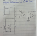
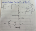
Schematics are below and which one is better solution ? I cant find a way to solve this probelm , please help me
1789632319727.png
1789632395736.png
and also are buffer op-amps necessary to stable the voltage level ? and Do they get slower the response time if I use them in current feedback path ?
 

Thread Starter

mazers

Joined Mar 3, 2026
13
Vo = 60V is fixed , Max. output current is 60A . Other charging current options will be 50A and 45A . and I couldnt see anything about the topic in UCC28950 datasheet and appliction information
 

schmitt trigger

Joined Jul 12, 2010
2,226
If you change your feedback loop gain, their phase/gain margins may be exceeded under certain conditions and the device may oscillate. Unless you compensate for the worst case scenario.
Loop compensation is not a trivial matter, and I would say that most if not all of the DIY SMPS supplies won’t have it optimized, to use a charitable description.
Therefore I believe it is better to adjust the reference voltage, and leave the loop gain always fixed.
 

MisterBill2

Joined Jan 23, 2018
28,253
ALMOST ALWAYS, adjusting the setpoint is the better choice than adjusting the gain. EXCESS gain will lead to instability and then oscillation, OR MUCH WORSE!!
THAT is why I suggest changing the setpoint.
ALWAYS keep the information as to what was set where before you changed it!!
ALL of the earlier cautions are right! tweaking adjustments can mess things up terribly!!
SO you wait until you know what you are doing!!
 

Ian0

Joined Aug 7, 2020
13,276
It depends on the error amplifier. If it is a conventional op-amp then the lower feedback resistor does not appear in the gain equation as it is a virtual earth amplifier, so in that case, it doesn’t matter which you adjust. However, if it is a transconductance amplifier then both feedback resistors affect the gain, in which case you should adjust the reference. (So the safe choice, if you are not sure what’s inside the controller Ic is to switch the reference). In both cases you don’t need an extra buffer.
a third choice, if you have a processor with a DAC, is to use the DAC output as the reference, and power the processor from an accurate voltage regulator such as the LP2951
 

Thread Starter

mazers

Joined Mar 3, 2026
13
thank you so much , I will go with resistor dividers with mosfet control and for you I should adjust the reference I got it . However, If I dont use buffer op-amp in reference path , the resistor dividers are connected to error amplifier network so Does it change characteristics of error amp. ? Thats why I thought that I need to use a buffer op-amp to hold voltage ?
Could you explain why is buffer op-amp not necessary ?
 

Ian0

Joined Aug 7, 2020
13,276
thank you so much , I will go with resistor dividers with mosfet control and for you I should adjust the reference I got it . However, If I dont use buffer op-amp in reference path , the resistor dividers are connected to error amplifier network so Does it change characteristics of error amp. ? Thats why I thought that I need to use a buffer op-amp to hold voltage ?
Could you explain why is buffer op-amp not necessary ?
The error amplifier is an op-amp. Its inputs will be high impedance, almost the same as the op-amp you are using as a buffer.
 

ci139

Joined Jul 11, 2016
2,033
what i'm able to see about the
buffer op-amp
is that - in case of fast transitions and weak input signal - the strength of f~e~e~d~b~a~c~k nets might interfere with your input - though it introduces delay for signal fronts - it actually should enable more true output at cases
 
It seems that the load is powered both directly by the battery bank and also by the charging system, which probably means that THE CHARGING SYSTEM MUST BE CAPABLE OF POWERING "THE WHOLE SHOW" under the normal operating conditions.
What makes the most sense is that the whole system is powered by a "MAIN POWER SUPPLY" and the battery system is kept fully charged as an instant backup.
Probably that is the existing plan, and the serious challenge is assuring that it actually works that way.

So actually we are being asked to design the system power supply and also the battery backup system.

AND to do it for free!

It is an interesting project, though.
BTW, what is a "PSFB converter",mentioned in the introduction but never defined in detail.
 
Top