ADC input works with potentiometer but not with AC signal from sensor!!?

Thread Starter

ashokraj

Joined Feb 1, 2018
151
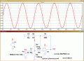
I am trying to convert a signal from accelerometer to a digital value. The output coming from accelerometer is in mv so I have added a non inverting voltage amplifier, then too I am getting a dc voltage at the output of opamp so I have added two capacitors to eliminate dc voltage in my signal. Here are my issues,

When I tried have connected a potentiometer to pin A1 and tried, I didn't find any issues, ADC is working perfectly but when I am trying to connect the output from the capacitor to PA1 and ground, I could not able to get the reading from controller!!!! I mean the voltage across capacitor is dropping to mV . I have measured the voltage across capacitor in oscilliscope by not connecting to PA1 its working perfectly, peak to peak is coming at 4V when vibrating.. but the moment I connect the ouput from capacitor to PA1 and measure the voltage across PA1 to GND. its dropping to mV, because of which i cannot do the data acquisition.

the source driving is output from signal conditioner which provide a constant power to industrial accelerometer. http://www.pcb.com/products.aspx?m=482c05


Are there any hardware connections/ biasing I need to do for conversion of an AC signal?

I am using a STM32F429 discovery board, Keil, ADC is in interrupt mode. Kit is powered through USB via computer.
Below is the link for schematic
Sensor is below link
http://www.pcb.com/Products.aspx?m=601A02

MOD: transferred your image.

https://drive.google.com/open?id=10FeMGhZmuvYHY8jgEu6LIBO_OmTPIElD

Capture.JPG


Last edited:

bertus

Joined Apr 5, 2008
22,882
Hello,

The problem is with the single power supply.
When you put the ground of R3 to 1/2 the powersupply voltage, you will have a virtual gound.

Bertus
 

OBW0549

Joined Mar 2, 2015
3,566
You need to download the Product Manual for this accelerometer and study the General Operating Guide section CAREFULLY so you can learn how to use it properly.

In any case, you absolutely CANNOT capacitively couple a signal-- ANY signal-- into an ADC input without also providing a DC path for the ADC's input bias current-- either a resistor to circuit common, or a voltage divider between the ADC's Vref and circuit common so as to bias the ADC inputs to some DC level. The circuit diagram you posted has no such DC path, therefore the ADC will not work properly.
 

Thread Starter

ashokraj

Joined Feb 1, 2018
151
hi,
Is this specification data for the Acc type you are using.?
Note the excitation and the Vout Bias voltage.!!!
E
I have connected a signal conditioner which takes care of the excitation voltage of sensor Eric, yes that is the specification sheet i am working on.

The sensor gets the excitation voltage from signal conditioner, and to eliminate dc bias voltage i have connected the capacitor in series at the output of op amp
http://www.pcb.com/products.aspx?m=482c05
 

ebp

Joined Feb 8, 2018
2,332
I think others have covered most of the problems with the circuit, but I'll add one point:

When you AC couple into the ADC input you will have signals going negative with respect to "ground" for the ADC. If the ADC has protection diodes, this may be permissible, though the current transients can be quite high if the output of the op amp falls rapidly. Even if the protection diodes keep the input from being damaged, any such negative voltage may cause malfunction of other channels if the ADC is multiplexed.
 

OBW0549

Joined Mar 2, 2015
3,566
Even if the protection diodes keep the input from being damaged, any such negative voltage may cause malfunction of other channels if the ADC is multiplexed.
That's a very good point, and I have personal experience that says it's pertinent: while using a PIC18F1320 I found that while making conversions on one ADC input, I'd get large errors if any of the protection diodes on other inputs were forward biased.

It's a good idea to ALWAYS keep analog (and digital) inputs between Vss and Vdd. Otherwise, strange things have been known to happen with one of these chips.
 
Performance ENGLISH SI Channels 4 4 Sensor Input Type(s) ICP® ICP®
Output Range(Maximum) ± 10 V ± 10 V

How are you handling the output voltage swing ? ± 10 V
 

ericgibbs

Joined Jan 29, 2010
21,390
hi ashok,

If you use a rail2rail OPA eg:MCP6001/02 and a single supply voltage supply of +5V, this circuit will connect to the ADC input.
Vso swing about +2.5v so, no negative under swings and as the supply is only 5V , no over swing.
E
 

Attachments

ebp

Joined Feb 8, 2018
2,332
ICP accelerometers are "phantom powered" using a constant current source which presents a high impedance to the signal. This results in an DC bias on the signal that is reasonably constant but of uncertain magnitude. (I've designed and built circuitry for such transducers.)

The DC offset can be blocked with a capacitor if the time constant of the resulting circuit is adequate to allow the lowest frequency of interest with tolerable error. If capacitive blocking is unacceptable, then there is little alternative but to produce an adjustable DC offset nulling circuit. Regardless of the method, by the time the signal gets to the ADC input it must have a DC offset that is approximately at the midpoint of the ADC's input range (e.g. 2.5 V for a 0 to 5 V ADC input). Since acceleration is the differential of velocity with respect to time, reduction in velocity will produce a negative-going signal. Presumably this information is not unimportant.
 

Thread Starter

ashokraj

Joined Feb 1, 2018
151
hi ashok,

If you use a rail2rail OPA eg:MCP6001/02 and a single supply voltage supply of +5V, this circuit will connect to the ADC input.
Vso swing about +2.5v so, no negative under swings and as the supply is only 5V , no over swing.
E
Can I use LM324 in place of MCP6001/02?
 
Last edited:
Top