ADC for high-precision measurement.

Thread Starter

Bryce

Joined Aug 7, 2010
8
If your voltage is down as low as 1 - 2 mV then you may simply amplify the signal to get usable output.
That is my hope, now.

I am curious how the voltmeter input bias current / impedance may be affecting your readings.
It sounds like the sensor has a high impedance output.
.

My conclusion is that the voltmeter is very, very high input impedance. It's actually a pretty fancy one, I think. It autoranges from .1V to 100V with no physical button-pressing. I got two of them and a bunch of other test equipment including two logic analyzers (HP 16500C with four LA cards, and another one that also had a DSO), a data/pattern generator, and a bunch of other stuff for $200 from an electronics surplus place. I ended up spending another $100 on various probes and cables, but I can't complain too much I guess.

I tried amplifying the photodetector's output with a bipolar opamp and got nothing useful, so the photocurrent is definitely very small - I'll try a follower as you suggest. I think you're right that the sensor's output impedance is very high. I also have some FET input opamps around here somewhere, I think.
 
The LMC662 has ultralow input bias current (in the low fA range). The offset error is high, around 3 mV, but since it's the *relative* change you're interested in, this may not be a problem. It may not be the best choice, but it's one to try. Input range includes ground and output is rail to rail.
 
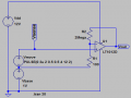
This may work... using an op amp with extremely low input impedance, and a stable voltage reference. The "Vmove" represents your photodiode. The "Vbase" serves to move it off of ground, for better results in the amplification, as well as to center it better in the ADC range of a microcontroller.

A very low input bias op amp allows the use of feedback resistance in the MegaOhms.

Noise / oscillation may be a problem, and judicious use of some low-pass feedback may be required in the real world.

By the way, I didn't use the correct op amp in the model. It's just a placeholder for the simulation.
 

Attachments

timrobbins

Joined Aug 29, 2009
318
I think you will find that the auto-ranging with the 3497A will not give you the same uV measurement stability or resolution when you have a circa 5VDC signal level - the 3497A is not that good. I have used one many years ago. It is basically a 5 and a half digit unit, and the FS range you would feed in to is 10V FS with 100uV resolution. You only get 1uV resolution on the 0.1V range.

If you try to AC couple that level of signal then you run into very long bias charging times with high impedance source, and very large cap where (depending on tech used) the parallel resistance may be an issue. It's a very ugly measurement scenario to have to battle through. I suggest you try and search for any recent (last 10-20 yrs) scientific papers on measurement techniques with the same scenario - they may quickly paint a picture of the measurement design areas you face. I would be keen to appreciate what recent measures can be thrown at this topic - and suggest that very high bit ADCs are the recent shining lights.

Ciao, Tim
 
Top