Facebook
 Google
 GitHub
 Linkedin
Hi Guys,
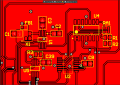
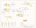
I have built a signal generator based on an AD9833 (schematic attached). The circuit is on a PCB. This is a second version of a circuit that already works. in the previous version I had a mechanical potentiometer to change the DC offset while now I'm using one of the available digital potentiometers. I can program all the chips and the AD9833 generates the waveform that I want. Something weir happens at the quad op amp...I have attached the waveforms I got probing different sections of the circuit. Anyone has any idea what's going on?
Thanks a lot for the help
Attachments
-
 260.8 KB Views: 134
 -
 909.8 KB Views: 134
 -
 909.8 KB Views: 118