Facebook
 Google
 GitHub
 Linkedin
I am undertaking this project to try and learn a bit more about electronics, wiring and motors. I am competent mechanically and have a rudimentary understanding of electrical systems, but I am very much a beginner.
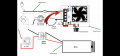
I currently have a DC motor that I wish to connect to AC power in a way which will allow me to control it's speed. I will be running the motor on average about 20 to 30 minutes, hour tops. I am not that concerned with achieving absolutely smooth RPM's but do not want to burn the motor out or cause other problems that could be dangerous.
The motor badge reads as follows...
Bodine electric motor
Volts: 130
HZ: DC
FF: 1.0
A: .91
HP: 1/8
Time: CONT
Ratio: 65.5:1
RPM: 38
Torq: 143 lb-in
I think I need to run a bridge rectifier between AC and the motor. I think I may need a capacitor if I wish to have smoother operation. Not sure if speed controller is best before or after the rectifier. Obviously I am new at all of this...
Anybody willing to breakdown what I might need to make this work? Including capability requirements of the controller and rectifier?
Again... I am trying to and willing to learn, so whatever help you might suggest I am open to listening.