 Facebook
 Google
 GitHub
 Linkedin
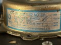
Picked up this motor the other day.. found out it's the blower motor from a Window AC unit. It's just the right size physically, to replace the motor in an older Lakewood HV fan. It appears to be a two-speed, high and low, but the diagram on the label is not 100% straightforward for me. I don't want to apply power and smoke it if I don't have to.
So my understanding currently is Red/Red are for the 5uf cap, I have a 6uf/250v to use. White is common and black and Yellow would be the speeds with Black being high, Yellow being low.
But the imagery.. how they decided to express the wiring connections is just so weird to me. I don't know what the symbol is between white and the intersection with red. And Yellow being a 'center-tapped' inductor.. perhaps that's how it's regulating speed because of a phase shift?
Or is it just like applying input voltage mid-way in the windings results in half the realized voltage?
Attachments
-
 2.3 MB Views: 30


