AC-DC Power supply failure

Thread Starter

cparke

Joined Aug 28, 2017
77
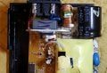
The attached image is my failed 120VAC 1.0A -> 30VDC 0.5A power supply. I'm trying to figure out what I need to change to fix it without changing everything.

I'm not an electronics expert, but looking at the board it has a transformer, one big capacitor and two smaller ones, a transistor attached to a heatsink, 2 filters, some diodes and resistors, and two other components that I'm not sure what they are. I understand this is a fairly common design.

The power supply actually still works when initially plugged in. But once a load is applied, it shuts down. So I'm hoping that's a big clue what component is probably failed. I'm thinking it's probably one of the capacitors, or maybe the transistor, but what do others here more knowledgeable about these things think?20220515_224930.jpg
 

dl324

Joined Mar 30, 2015
16,844
All of the white goop and yellow insulation indicates that high (i.e. lethal) voltages are present. Are you sufficiently competent to work around high voltages?

If you feel it's within your abilities, start by tracing the circuit and making a schematic.
 

Thread Starter

cparke

Joined Aug 28, 2017
77
I was wondering why they put that white stuff there! Makes it a pain to change those components. I guess it's related to the large 400V capacitor connected to the transformer, though I don't get why they would step up 120VAC to 400V just to later step it down to 30VDC.

At any rate, I'm particularly a bit puzzled how the MOSFET transistor functions in this circuit. I assume it's doing some sort of voltage regulation, but I was expecting a LM317 or something to do that!
 

Ian0

Joined Aug 7, 2020
9,667
I was wondering why they put that white stuff there! Makes it a pain to change those components. I guess it's related to the large 400V capacitor connected to the transformer, though I don't get why they would step up 120VAC to 400V just to later step it down to 30VDC.
They probably don't - is it a universal supply that will take a 230V AC input? If so, it needs a 400V capacitor. If not, they might just be using the same circuitry and changing the transformer
At any rate, I'm particularly a bit puzzled how the MOSFET transistor functions in this circuit.
Look up Flyback converter
 

Thread Starter

cparke

Joined Aug 28, 2017
77
is it a universal supply that will take a 230V AC input? If so, it needs a 400V capacitor.
That is, in fact, the case. It is designed to work off of both U.S. (120VAC 60Hz) and international AC (220VAC 50Hz) standards. As I am in U.S.A., I don't think there really is more than 120VAC going through this thing, on the primary side of the transformer of course.

Tracing the line is a bit confusing for me, especially when it comes the MOSFET. I really think the IC is switching the device off after detecting an error condition when load is applied, so tracing prior to the load will show no problems, and afterward will probably just show where it has been switched off (the transistor again?).

So I really don't think that approach is going to be helpful. Am I missing something? Testing individual components seems the only way, but I'd like a clue on the most likely culprits for this behavior.
 

Dodgydave

Joined Jun 22, 2012
11,284
What you have is a switchmode psu, which are not easily repairable for us experts , if it's shutting down its due to over current protection by the chip.
My advice is to bin it!
 
Last edited:

Irving

Joined Jan 30, 2016
3,843
The problem with repairing simple switch-mode power supplies like this is that when a component fails it often takes many other parts with it.

The incoming mains is directly rectified and smoothed by the big capacitor to give 150v DC (on 110ac, 300v DC on 220ac). A control IC switches the MOSFET on & off at high-frequency, typically 100 - 500kHz allowing the use of a much smaller ferrite cored transformer than an iron-cored one if it were operating at 60Hz. The transformer provides isolation from the mains supply to the output winding, which is rectified and smoothed with another capacitor, but as its a high-frequency this is often 50 - 100x smaller than it would be for a 60Hz system. Usually there is an opto-coupler and voltage reference on the output side (probably IC1 on that PCB, together with ZD52) that provides isolated feedback from the rectified output to the switching IC for voltage regulation. A large resistor off the rectified mains input provides the IC with just enough current to start, and another isolated secondary winding and rectifier/capacitor combo provides the IC with power to keep running after the soft start.

Its not uncommon for this latter circuit to fail with a broken winding so it starts OK but under load the IC isn't getting enough current to keep going and shuts down, which explains your symptoms - or exhibits squegging - switching on and off every few seconds.

Identifying the fault(s) is one thing, fixing it if it is an IC failure or broken transformer winding may not be possible or cost effective as these are often custom or proprietary parts.

As has been already said, a hi-res photo of the back of the board is essential, and you will need to remove, carefully, all the goop (or hot-snot as its commonly called) so we can see whats under there. The goop's main purpose is not as an insulator (though it is) but there to stop parts moving mechanically under electrical stress and making high-pitched sounds.
 

Ian0

Joined Aug 7, 2020
9,667
It's usually a faulty MOSFET, but the MOSFET could have failed because of a faulty secondary diode.
Check the diode on the secondary, and replace if faulty. Check the MOSFET and replace if faulty.
Damage to the control ICs is less common, so with a bit of luck you could have fixed it.
 

Irving

Joined Jan 30, 2016
3,843
In my experience its rarely a faulty MOSFET... A faulty MOSFET eg gate isolation failure wouldn't allow it to start at all and if failed drain/source s/c would usually take out primary winding which is often obvious - burnt components or PCB tracks and/or blown primary side fuse - which looks to be intact. It could be localised heating in the MOSFET causing it to go o/c after startup, rare and can be hard to test for as it'll check out OK at static DC.

But I'd be wary of advising the TS on fixing it themselves unless they are comfortable working with HV DC and have the requisite test gear (ie as a minimum a cat III 600V certified multi-meter).
 

dendad

Joined Feb 20, 2016
4,451
I would advise you to give this job a miss.
These switch mode power supplies can be lethal and unless you know what you are doing, great harm can result. Definitely not a job for a novice.
At least read up on how they work, and do not poke around it while it is plugged in.

If you need another 30V supply, you may be able to pick up an old HP printer 32V supply and feed the output through a 2 or 3 series diodes to reduce the 32V to 30V if 32V will nor work for you. These power supplies are often chucked out along with the old printer so you should be able to get one for free.
 

Irving

Joined Jan 30, 2016
3,843
@cparke What was this PSU for? 30v, 15W supplies can be picked up for a few $$ on Amazon, its probably not worth the hassle fixing it.

[edit]
DELTA ADP-15NH A POWER SUPPLY 30VDC 0.5A 21G0325 FOR LEXMARK/DELL PRINTERS
can be picked up new for $25 or less... or used on eBay for $10-12
 
Last edited:

Alec_t

Joined Sep 17, 2013
14,280
Even if you could fix the supply, you should ask yourself why it failed. If it was due to a current overload, then the load being driven by the supply might itself be faulty. If so, a repaired/new supply is likely to fail.
 

Irving

Joined Jan 30, 2016
3,843
Even if you could fix the supply, you should ask yourself why it failed. If it was due to a current overload, then the load being driven by the supply might itself be faulty. If so, a repaired/new supply is likely to fail.
Good point - the fact it shuts down on load - if the load is the printer its intended for - might actually be a fault in the printer and not in the power supply!
 
Last edited:

Thread Starter

cparke

Joined Aug 28, 2017
77
The problem with repairing simple switch-mode power supplies like this is that when a component fails it often takes many other parts with it.
I'm hopeful that's not the case, particularly as it still works without a load present.
Its not uncommon for this latter circuit to fail with a broken winding so it starts OK but under load the IC isn't getting enough current to keep going and shuts down, which explains your symptoms - or exhibits squegging - switching on and off every few seconds.
That sounds like what could be happening. When you say "winding", are we talking about the actual transformer? Is there any easy way to test a transformer winding for this condition?
As has been already said, a hi-res photo of the back of the board is essential.
I certainly can post a photo the back side that if folks here are interested in working with me further to figure this out. Let me know. There's really nothing discernible on the back that I would contemplate replacing, mostly there are many of these little black modules with numbers on printed them, which I guess are some kind of resistors?
@cparke What was this PSU for? 30v, 15W supplies can be picked up for a few $$ on Amazon, its probably not worth the hassle fixing it.
Good point - the fact it shuts down on load - if the load is the printer its intended for - might actually be a fault in the printer!
You guys are right, this is for a printer. The cause is not the printer, however. This power supply has failed for me before and been replaced, it seems like they only last about 5 years or so. Printer is also running fine on a 24V SLA battery hook-up until I get this resolved. And yes, I can still get another of these power supplies (used) pretty cheap and that is the easiest solution.

My point in posting here, however, is that I would like to figure out what goes wrong on this circuit, as this particular model is out of production for many years now, and as time goes on it will get harder to find a replacement. And there's a risk the replacement I get may have the same problem since this tests out fine without a load. Certainly, in worst case, I could also rig up some re-wiring to a separate, external power supply, but if a simple failed component that can be replaced easily enough can be identified as the cause, I would prefer that route in the future.
 

michael8

Joined Jan 11, 2015
410
I have one small switching supply which had an output capacitor fail. This resulted in excessive output voltage
which flowed through the zener across the output of the supply. The zener went short circuit. I replaced
the output capacitor & zener to fix it.
 

Thread Starter

cparke

Joined Aug 28, 2017
77
I have one small switching supply which had an output capacitor fail. This resulted in excessive output voltage
which flowed through the zener across the output of the supply. The zener went short circuit. I replaced
the output capacitor & zener to fix it.
Good information. But in that case, the power supply went permanently dead until repaired?
 

Irving

Joined Jan 30, 2016
3,843
I have one small switching supply which had an output capacitor fail. This resulted in excessive output voltage
which flowed through the zener across the output of the supply. The zener went short circuit. I replaced
the output capacitor & zener to fix it.
I must have fixed dozens of these over the years, and the number of ways they can fail is huge. You might have got lucky on a simple fix but the chance of that being the reason for this failure is minuscule.

Personally I wouldn't bother fixing this. I'd confirm the printer is only taking the 0.5A the PSU is rated for and then replace the PSU with a bigger one rated at say 1A or more. The likelihood is that the printer takes an average of <0.5A most of the time with spikes of just over that. Over the years the stress on the PSU builds up until it eventually fails; these things are built down to a price. There's probably little that can be realistically done to make it more reliable as these are not designed specifically for that printer but are generic designs manufactured by Delta and badged for the printer manufacturer. Lexmark will have done their failure analysis and it'll say MTBF (mean time between failures) is approx 3y, and they'll go, Hey, that's good enough for the price we pay (around $4 or less) and won't drop us into too many warranty replacements within 1 - 2y or whatever the warranty period is (probably 1y mostly).

@cparke Without a step-by-step analysis and investigation clutching at other people's straws doesn't help. If you want to fix it as a learning exercise on how SMPS' work then I'm happy to guide you through the process. However, be aware that it may not be fixable with the knowledge and tools you have as remote diagnosis is not always possible. Also you are working with high, potentially lethal, voltages at your own risk. When I work on such devices I use a isolating mains transformer with an RCD to avoid shorts to ground and always work one-handed on the mains side to avoid accidentally putting 300v across both hands - that tends to be painful at best, lethal at worst!

Step 1 is to give us good photos of both sides of the board with goop removed so we can assess what one of several possible arrangements is being used here and what controller IC is used.
 

Thread Starter

cparke

Joined Aug 28, 2017
77
Personally I wouldn't bother fixing this. I'd confirm the printer is only taking the 0.5A the PSU is rated for and then replace the PSU with a bigger one rated at say 1A or more. The likelihood is that the printer takes an average of <0.5A most of the time with spikes of just over that. Over the years the stress on the PSU builds up until it eventually fails; these things are built down to a price.
I agree. There probably are surges over .5A when the motors starts up, for example. While I have the battery hook-up arrangement still in place, I will add an amp meter and try to verify how much current is actually being drawn.

If you want to fix it as a learning exercise on how SMPS' work then I'm happy to guide you through the process. However, be aware that it may not be fixable with the knowledge and tools you have as remote diagnosis is not always possible. Also you are working with high, potentially lethal, voltages at your own risk. When I work on such devices I use a isolating mains transformer with an RCD to avoid shorts to ground and always work one-handed on the mains side to avoid accidentally putting 300v across both hands - that tends to be painful at best, lethal at worst!
That is what this is (a learning exercise for myself and others who may read this forum in the future), and it is well understood that there may not be a happy ending for the power supply (which is otherwise junk already). It would be a bonus if I get it working again, but yes more interested in just finding out what went bad. Your warning is well taken, and I will be using a GFCI outlet when energizing to reduce the shock risk while examining the components. I also have been discharging the capacitors already when examining on the bench, the 330 micro-farad one has consistently been generating a spark when shorted out which is a sign that it is good.

Step 1 is to give us good photos of both sides of the board with goop removed so we can assess what one of several possible arrangements is being used here and what controller IC is used.
Great, I will work on getting that up here tonight.
 

Thread Starter

cparke

Joined Aug 28, 2017
77
Etched off some of the "goop" to reveal hidden components, mostly diodes it seems. The bridge rectifier (4 diodes) is under the large 400V capacitor, and the transformer seems to be on the DC side and involves 3 connections on both sides (though the is also a 4th pin on one side, but I'm not sure if that is just grounding or something). No clue what the two clear wires going into the transformer from above are for, except maybe a thermometer or ammeter? The heatsink on the MOSFET seems to extend to a small flat metal panel on the bottom. New photos below/attached for better details of power supply board.

Re-checked the board also to make sure I didn't break anything, and yes it's still working the same as before. In fact, connected the broken power supply to a 4300 ohm resistor too, and it was able to put out 7mA (0.21 watts) without shutting itself down (still can't handle powering the printer, however).

FYI - powered up the printer connected to battery with an ammeter attached, and I found that while the printer generally uses less than 500mA (only around 200 mA when awake and not printing, which I think the broken power supply can even handle), but during actual printing there are frequent but brief surges to as high as 750mA. I think Lexmark indeed spec'd this power board to die slowly by design through constant spike overloads like this that the IC can't respond to in time.

Any questions about what you see in these photos? What components should I check first?
20220517_100858.jpg20220517_100914.jpg20220517_100930.jpg20220517_100945.jpg20220517_101022.jpg20220517_101109.jpg20220517_101036.jpg20220517_101046.jpg
 

Attachments

Last edited:
Top