 Facebook
 Google
 GitHub
 Linkedin
Hi I'm having some confusion drawing the phasor diagrams for the current and voltage. Did some research on the net and the text book. Still I'm confused. Can't one draw the V and I with the phase angle difference. Does it have to be a certain way for series circuit and another way for parallel circuits? and my teacher was not very clear about this when I asked him. He mentioned something about the impedance diagram which added to the confusion even more :S.
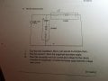
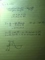
I've included the question and the way I worked it out.
Ignore the work done on the question paper.


I've included the question and the way I worked it out.
Ignore the work done on the question paper.


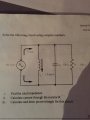

") . Going back to the question with series and parallel components how would I draw the phasor diagram when it has got series and parallel components. Is my approach right? Im referring to #6 post up
. Going back to the question with series and parallel components how would I draw the phasor diagram when it has got series and parallel components. Is my approach right? Im referring to #6 post up


