 Facebook
 Google
 GitHub
 Linkedin
Hello everyone !
Have already asked a similar question today but would like to change it a little bit:
1. Can you please explain in your own words how radio tuner works (of AM)
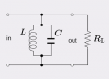
2. Can we assume that the bandpass filter, shown below, is of radio tuner ?
Have already asked a similar question today but would like to change it a little bit:
1. Can you please explain in your own words how radio tuner works (of AM)
2. Can we assume that the bandpass filter, shown below, is of radio tuner ?
Attachments
-
 2.9 KB Views: 18


