 Facebook
 Google
 GitHub
 Linkedin
Hi everyone !
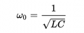
Have the following question: in a parallel LC, how does resonance occur ? Many sites suggest the typical formula (see below), but at this one the impedance is actually at maximum....
Could you help me ?
Have the following question: in a parallel LC, how does resonance occur ? Many sites suggest the typical formula (see below), but at this one the impedance is actually at maximum....
Could you help me ?
Attachments
-
 8.5 KB Views: 14


