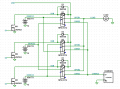
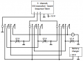
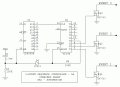
I just had a DUH moment while at the bank. In my circuit, the six relays are activated in three fixed pairs. This means that that 6 x SPST can be replaced by 3 x DPST. I think it cooks down to the Nandu circuit in #127.
I just had a DUH moment while at the bank. In my circuit, the six relays are activated in three fixed pairs. This means that that 6 x SPST can be replaced by 3 x DPST. I think it cooks down to the Nandu circuit in #127.
I just had a DUH moment while at the bank. In my circuit, the six relays are activated in three fixed pairs. This means that that 6 x SPST can be replaced by 3 x DPST. I think it cooks down to the Nandu circuit in #127.
OK, try this. Reduced relay assignments, power-on reset. The TS has been pretty clear about it not being a problem for the charger to be connected to the Operate bus *briefly*, so I left out cross-conduction protection.
If the relays are driven by FETs, the transient suppression diodes (D1 - D3) could be deleted because FETs have internal zener diode clamps.
Sorry, my sentence was meant to say ‘now found a solution’ instead of ‘not found a solution’.
These experienced engineers have contributed to a practical solution to a practical problem. What’s to complain about? That’s what engineers do . . .
The TS has be pretty clear about it not being a problem for the charger to be connected to the Operate bus *briefly*, so I left out cross-conduction protection.
But given that there is also the possibility of two Devices (batteries) being momentarily connected together, which could generate a large momentary current and a large arc when the contacts open, I think preventing that is worth the extra resistor, diode, and capacitor for each MOSFET driver shown in my post #139.
Not sure that's true for all FETS.
If you notice in the datasheets, some MOSFETs show a Zener symbol for the substrate diode (indicating it is avalanche rated) and some show a standard diode symbol.
For example, I see no mention of that in the 2N7000 data sheet I looked at so I suspect it is not.
Yikes! Well, I will have to go with the one I'm in the middle of, after doing all the follow-through, but if it doesn't work or is problematic, then I will give this a try.
Can you elaborate on the 3-shot monoshot (monostable?) timer? Is that 3 x a '555', with associated circuitry, and with pin 3 from each of them being the '1,2 &3' in your diagram? If so then I expect that each of the 555s can share the RC networks for simultaneous function.
Yes, the three-channel sequence timer has three discreet 555 monoshots wired in sequence, with the output of each one of them (pin 3) triggering the following one. The outputs '1', '2' & 3 drive the relays. The RC networks cannot be shared.
No, device 1,2&3 are separate devices (batteries in this case) and they each in turn drive the same load. Equally they are charged in turn by the same charger. The load and charger are not shown on the schematic except as ‘Device Power Out’ and ‘In’
So you are not considering changing to Nandu's circuit which halves the number of relays and reduces the amount of wiring?
It adheres to the KISS principle, which I try to follow.
Edit:
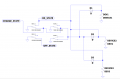
Below is a delay-on, no-delay-off, driver circuit that could be used to drive the three relays to prevent overlap:
Yes, I'm considering it but it means scrapping three days of work on the schematic and PCB design . . . .Your attached circuit is in place of the 3 channel 'Monoshot' device?
All this to avoid using a microcontroller. 14 pin PIC, capacitor, 6 SPDT relays, 6 MOSFETs, 6 flyback diodes, and you are done. A switch to advance manually if you still want that. Can update, change the timing, change the sequence at will via programming. If an engineer working for me proposed what is proposed here, they would be fired.
I have explained earlier why a Microprocessor is not the way I need so I guess you missed that; and most of us would agree that three relays are 'better' than 6, let alone the 6 MOSFETs your version requires. I'm not looking for the most elegant solution but the most useful in my context - a big difference.
My circuit is post #139 is to show the delay circuit to prevent relay overlap in the 3 relay configuration.
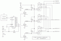
The complete 3-relay circuit (without the delay circuit, which I think should be added) is shown in AG's post #145.
The "Monoshot" device is still the CD4017 counter and 4060 oscillator.
On-State is connected permanently to all three devices, and Charge-State is permanently connected through diodes. Also, both are shorted directly to GND by the relays.
Yes, the three-channel sequence timer has three discreet 555 monoshots wired in sequence, with the output of each one of them (pin 3) triggering the following one. The outputs '1', '2' & 3 drive the relays. The RC networks cannot be shared.
Three 555's in a circle (sometimes called a ring oscillator) will work, and allows for individually adjustable output periods. However, the standard monostable circuit will not work without a differentiator at each Trigger input.
For long time delays I think you get more consistent performance with an oscillator and divider / counter. Also, a circuit with three 555's needs something to assure stable operation at power-up. Without that, all three outputs might be on at the same time. As in the schematics so far, a counter with a POR circuit avoids this.
Which reminds me - the POR added to the 4017 can also drive the 4060, so the first cycle is not randomly shorter than succeeding cycles. To do this in the #145 schematic, C1 and R1 are moved to the 4060 Reset pin, a diode connects this node to the 4017 Reset input (along with the feedback diode from the "4" output), and a resistor to GND is added to assure the Reset input rests at the low state.
Yes, I'm considering it but it means scrapping three days of work on the schematic and PCB design . . . .Your attached circuit is in place of the 3 channel 'Monoshot' device?
I have explained earlier why a Microprocessor is not the way I need so I guess you missed that; and most of us would agree that three relays are 'better' than 6, let alone the 6 MOSFETs your version requires. I'm not looking for the most elegant solution but the most useful in my context - a big difference.
The relay arrangement is independent of using a microcontroller. Except for the fact that the microcontroller is able to prevent overlap without the cross linked relays, which gives you more flexibility for the relays. Again, the point goes to the microcontroller.
I don’t think I have seen a three relay solution that prevents overlap and handles the idle state. But then so many schematics.
And no, I did not miss your reasoning, I maintain that it is wrong. Here is what you said:
Yes I’m sure it could be done with suitable processing power from an Arduino etc but I’m thinking less complex or sophisticated and using ‘simple’ electromechanical relays and some logic sequence. I see it more as a challenge in arranging some relays to provide the sequence in the table.
Here is a *concept* schematic showing how to combine the power-on-reset circuit for both ICs. Note that the oscillator components, decoupling, clock source selection, etc, have been omitted for clarity.
At power-on, C1 is discharged. It pulls both Reset inputs high, resetting both parts. This forces U2 pin 7 low (if it isn't already), but C1 briefly overpowers both R1 and R2. As C1 charges through R1 and R2, the reset voltage decreases to zero, releasing both parts to start counting. At this point, D4 disconnects R1-C1 from R2 and the U2 pin 7 output, so subsequent U2 resets do not affect U1.
The Reset time is approx. 40 ms. The CMOS threshold level is approx. 50% of Vcc, which is 0.7 x R x C. R is R1 in parallel with R2, but this is modified by the presence of D4.
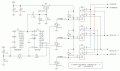
I didn't think it was necessary, but here it is -- 3 DPST relays, overlap protection, and dual POR.
Crutschow's version of overlap protection has an R-C delay network at each driver transistor gate or base. I think both methods have pluses and minuses. In body count, the tradeoff is one small power transistor versus 6 little parts. Depending on the relay coil power, doing the delay at the low power level might have a clear advantage.

 Facebook
 Google
 GitHub
 Linkedin